Manifold

A water separator and water outlet technology, which is applied to sliding valves, engine components, mechanical equipment, etc., can solve the problems of high resistance and labor, and achieve the effect of small operating stroke, long service life and large flow.

Pending Publication Date: 2019-11-22
ZHEJIANG SUERDA SANITARY
View PDF1 Cites 1 Cited by
  • Summary
  • Abstract
  • Description
  • Claims
  • Application Information

AI Technical Summary

Problems solved by technology

[0004] The diverter valve in the above-mentioned patent documents drives the valve stem to move axially by pressing, so as to realize the switching of different water outlets. The principle is the same as that of the existing pull-type diverter structure, and the resistance is greater when the water pressure is high. , more strenuous

Method used


Image

  • Manifold
  • Manifold

Examples


Embodiment Construction

[0024] The following are specific embodiments of the present invention and in conjunction with the accompanying drawings, the technical solutions of the present invention are further described, but the present invention is not limited to these embodiments.

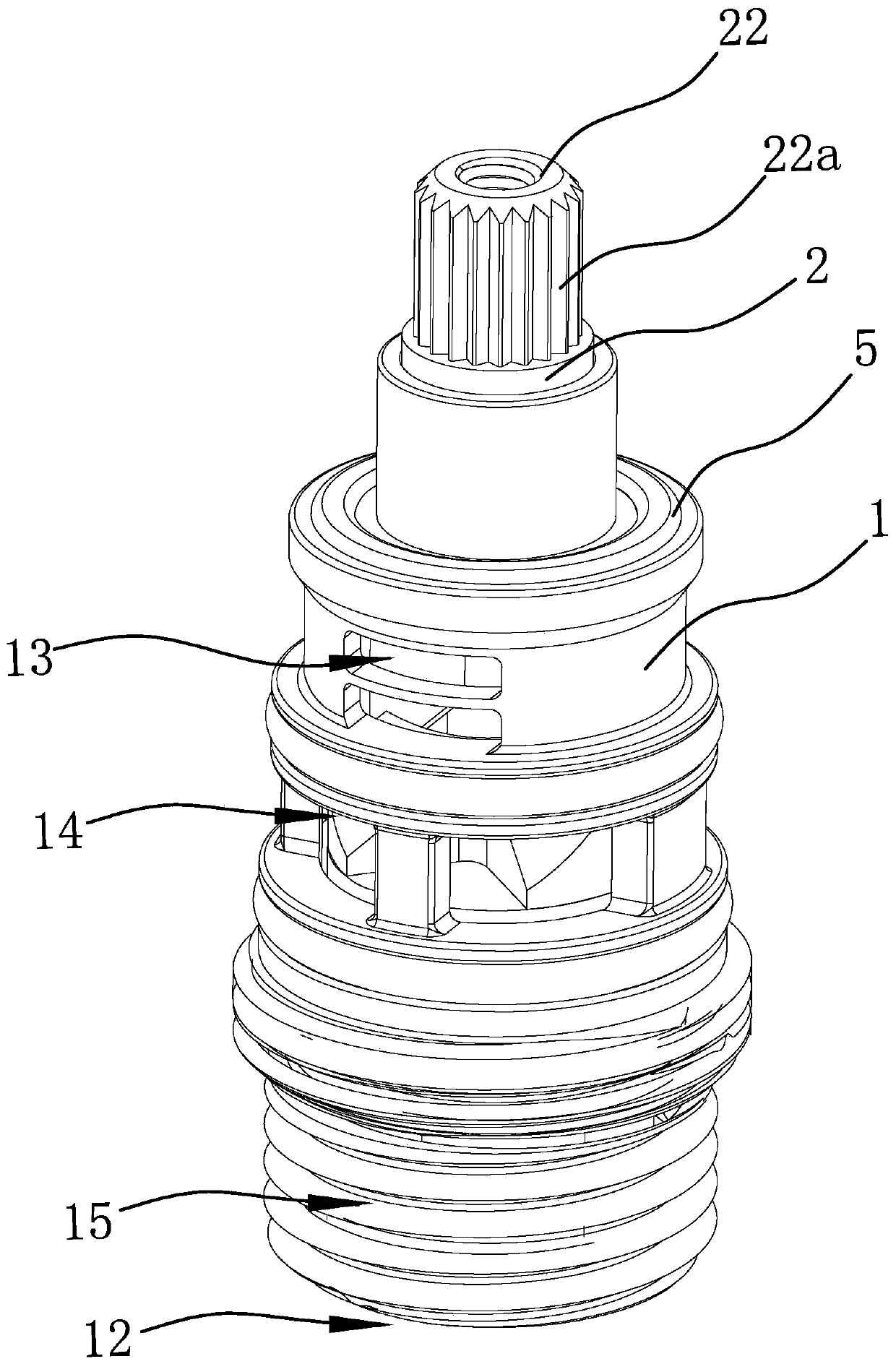
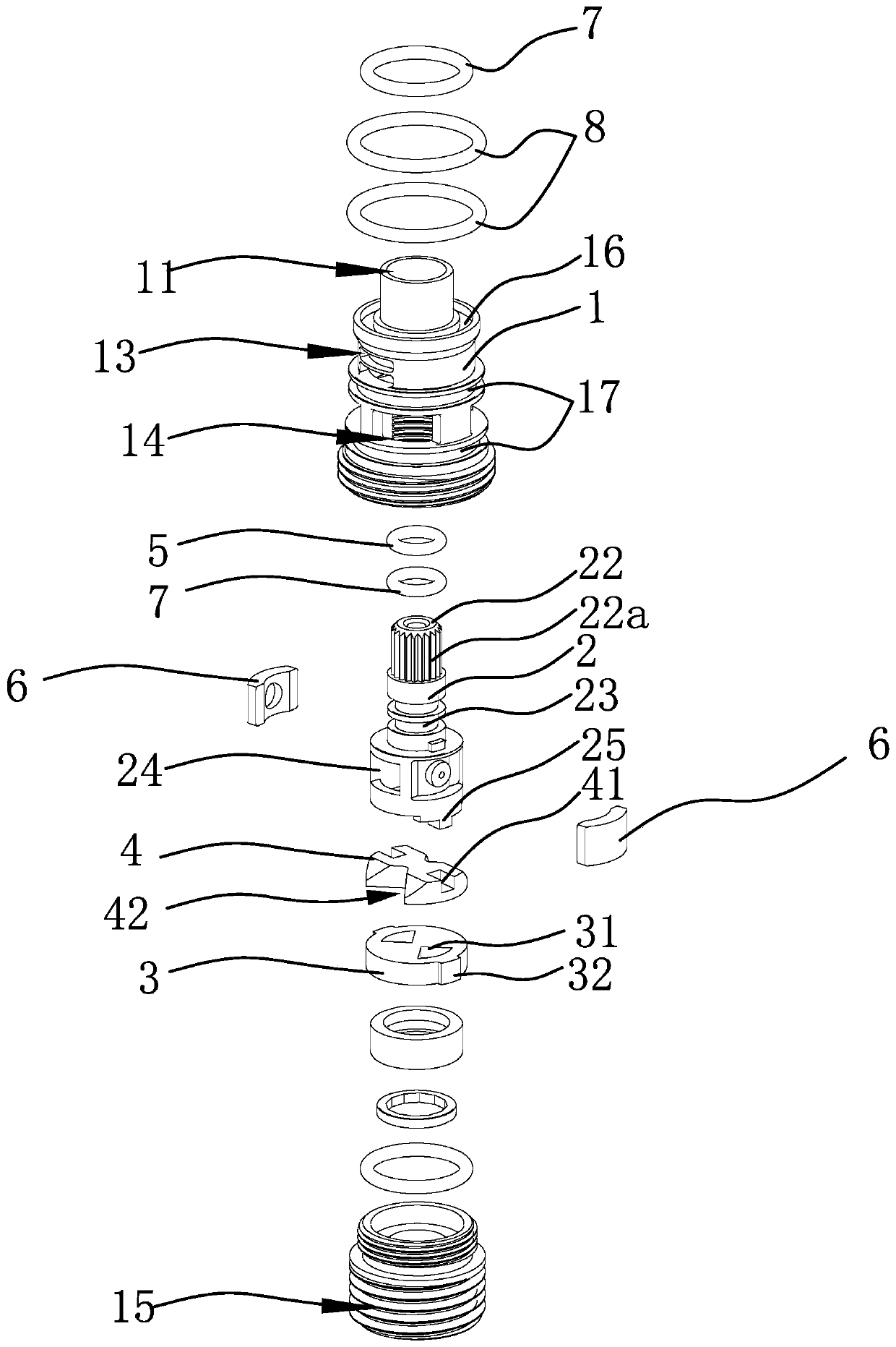
[0025] Such as figure 1 and figure 2 As shown, the water distributor includes a valve body 1 and a valve stem 2. The valve body 1 has a through hole 11 penetrating in the axial direction. The lower end of the valve stem 2 is rotatably inserted in the through hole 11 of the valve body 1. The valve stem The upper end of 2 protrudes upwards beyond the upper end of valve body 1, and the lower end face of valve body 1 has water outlet one 12, and the outer peripheral surface of valve body 1 is respectively provided with water outlet two 13 and water inlet 14, and water inlet 14 is positioned at outlet. Between the water outlet one 12 and the water outlet two 13, the through hole 11 of the valve body 1 is located between the w...


PUM


Abstract

The invention provides a manifold, and belongs to the technical field of valve equipment. The manifold solves the technical problems that an existing manifold is difficult to use, low in flow and thelike. The manifold comprises a valve body and a valve rod, wherein the valve body is provided with a penetrating through hole in the axial direction, the lower end of the valve rod is rotatably inserted into the through hole of the valve body, the upper end of the valve rod extends out of the upper end of the valve body upwards, a water outlet I is formed in the end face of the lower end of the valve body, a water outlet II and a water inlet are formed in the outer peripheral surface of the valve body correspondingly, a water inlet is formed between the water outlet I and the water outlet II,a plugging circular plate is arranged in the through hole and between the water inlet and the water outlet I, the outer peripheral surface of the plugging circular plate is in sealing connection withthe inner wall of the through hole, and the plugging circular plate is provided with a water passing hole I which penetrates vertically; and the lower end of the valve rod is connected with a rotary plate and can drive the rotary plate to rotate, and the side part of the lower end of the valve rod is provided with a plugging part capable of plugging or opening the water outlet II during rotation.The manifold has the advantages that the flow is large and the labor is saved.

Description

technical field [0001] The invention belongs to the technical field of water supply valve equipment and relates to a water separator. Background technique [0002] With the improvement of living standards, people have higher and higher requirements for water supply valves. For example, in shower equipment, it is not only required to be able to control the water temperature and flow rate, but also to be able to switch between different spraying methods. This function usually requires a water separator. to realise. The water distributor is a water distribution device specially used to connect various water supply pipes. At present, the water distributor is widely used and has a variety of types. The existing water distributor switching control technologies on the market mainly include pull rod structure, horizontal dial structure and rotary The basic principle is to open four or two water inlets on the valve body, and then cooperate with the rotation between the ceramic movin...

Claims


Application Information

Patent Timeline
Patent Type & Authority Applications(China)
IPC IPC(8): F16K3/08F16K3/314
CPCF16K3/08F16K3/314
Inventor 李军
Owner ZHEJIANG SUERDA SANITARY
Why Eureka
Try Eureka