LED lamp being changeable in light emitting angle and range

A technology of LED lamps and light emitting angles, which is applied to semiconductor devices, light sources, electric light sources, etc. of light-emitting elements, can solve problems such as damage, and achieve the effects of low cost, wide use places, and easy adjustment of light emitting angles and ranges.

Pending Publication Date: 2019-11-22
SHENZHEN HTA LED LIGHTING ELECTRONICS CO LTD
View PDF0 Cites 0 Cited by
  • Summary
  • Abstract
  • Description
  • Claims
  • Application Information

AI Technical Summary

Problems solved by technology

For the existing floodlights, one lamp can only provide one light emitting angle and irradiation range. If the same lamp wants different light emitting optical angles, the whole lamp needs to be replaced
[0003] In addition, the existing floodlight generally has the optical components and the power supply in the same cavity. For the structure of the lamp driver in the same direction, maintenance and replacement of the internal components of the lamp body, such as the power supply or optical devices, requires the entire lamp to be disassembled. The parts that need to be replaced are prone to human damage risks

Method used


Image

  • LED lamp being changeable in light emitting angle and range
  • LED lamp being changeable in light emitting angle and range
  • LED lamp being changeable in light emitting angle and range

Examples


Embodiment 1

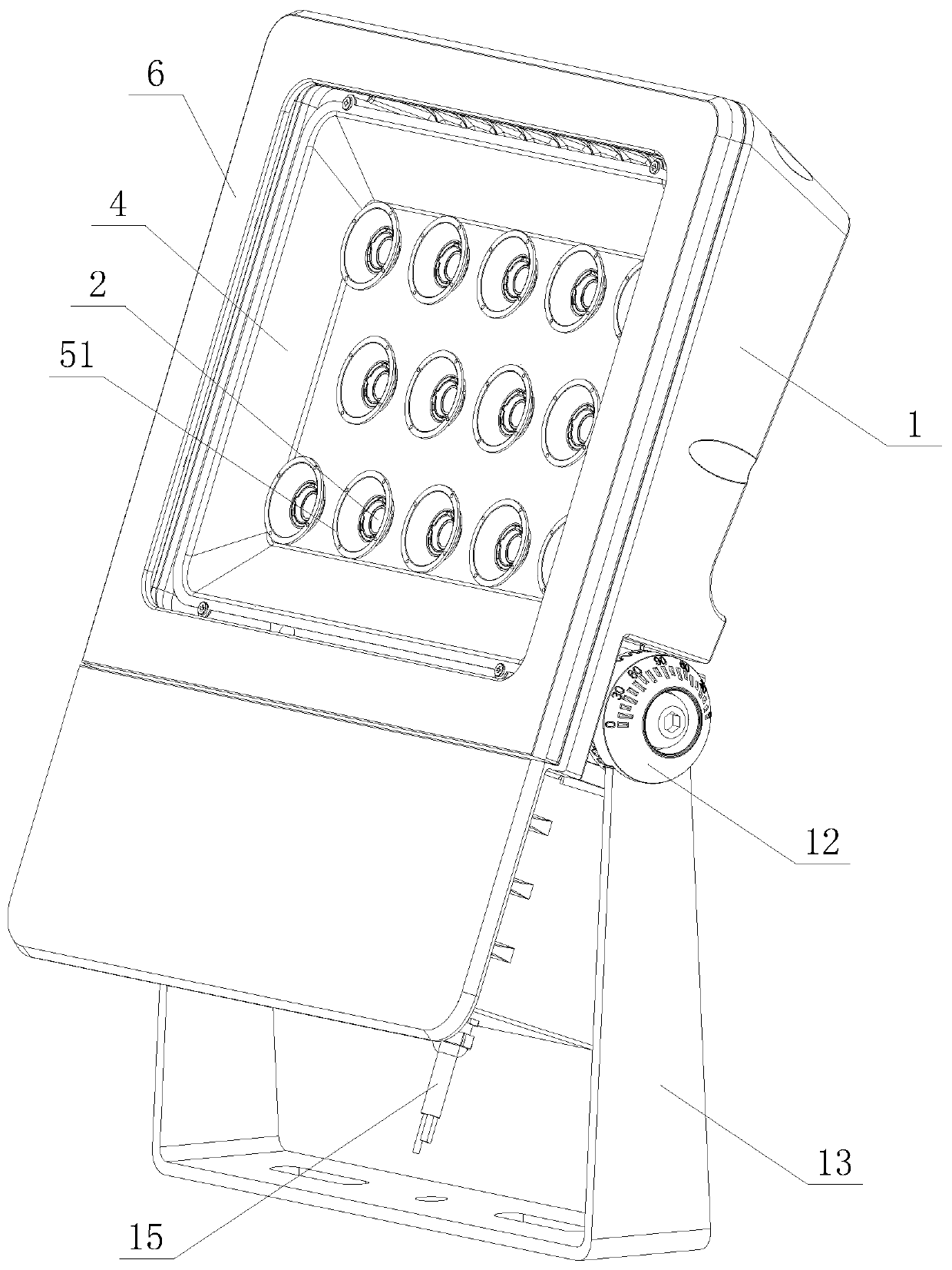
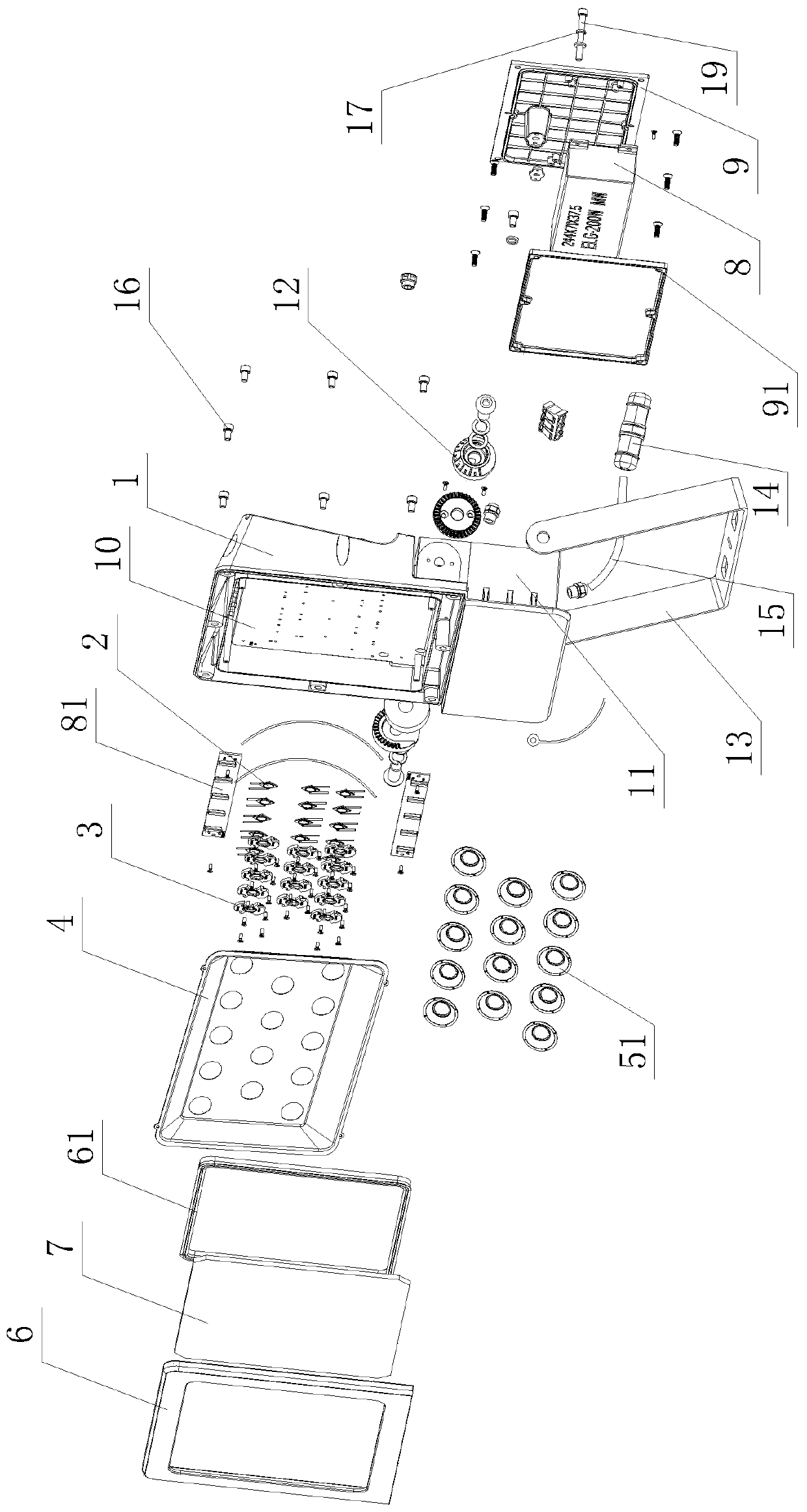
[0029] like Figure 1 to Figure 5As shown, the LED lamp of this embodiment that can change the light output angle and range includes a lamp body 1, fourteen LED lamp beads 2, fourteen reflective cup holders 3, flood reflectors 4, a group of fourteen in total Concentrating reflector 51, the front of the lamp body 1 is provided with a light source compartment 10, fourteen of the LED lamp beads 2 are arranged in the light source compartment 10, and the fourteen of the LED lamp beads 2 are arranged in an array , divided into three rows, the flood reflector 4 is set on the inner periphery of the light source compartment 10, each of the reflective cup holders 3 is set corresponding to one of the LED lamp beads 2, and the LED lamp beads 2 are COB As a light source, the condensing reflective cup 51 is detachably connected to the reflective cup holder 3, and the center of the reflective cup holder 3 is provided with a first central hole 30 for making way for the LED lamp bead 2. Above...

Embodiment 2

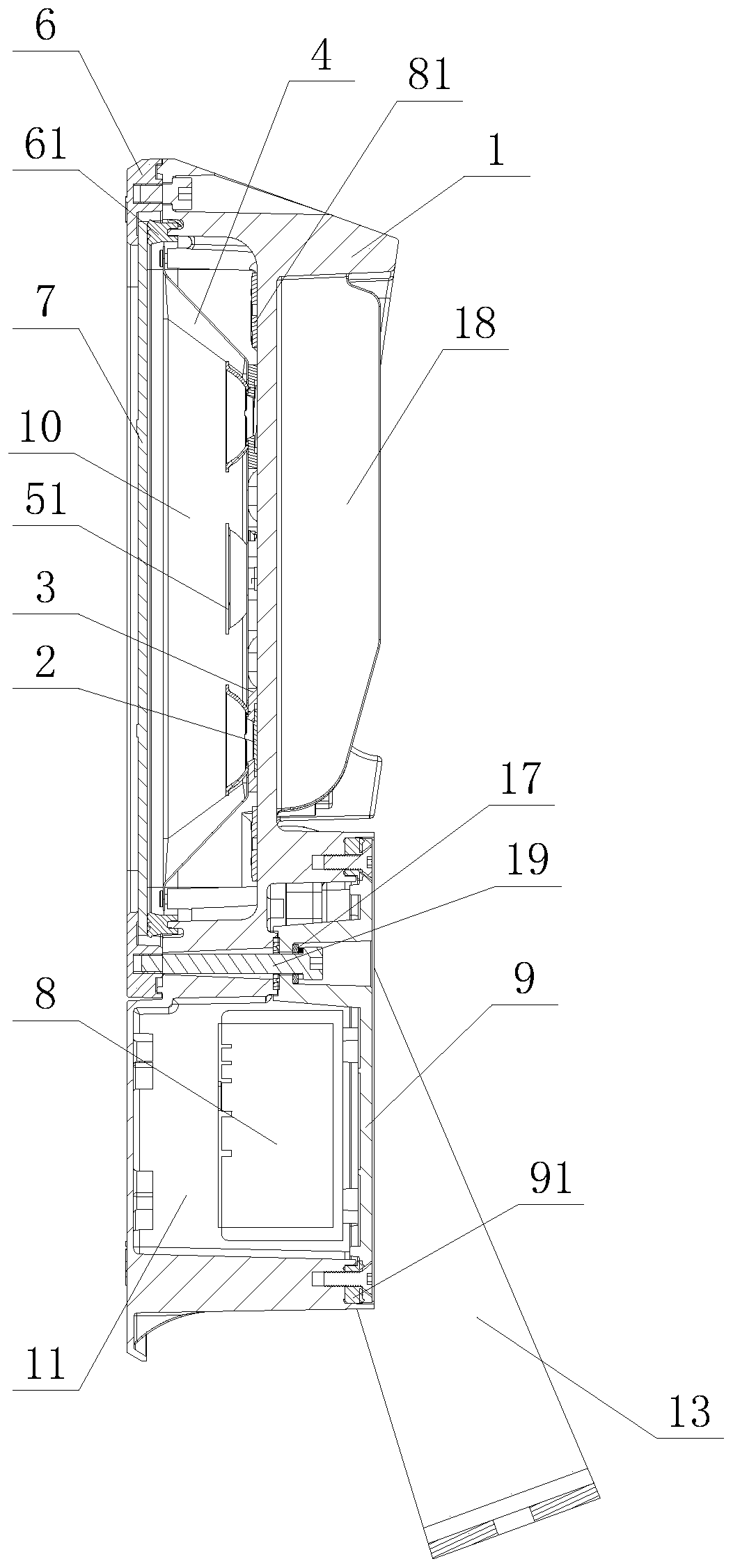
[0031] like Image 6 , Figure 7 As shown, the difference between this embodiment and Embodiment 1 is that: in this embodiment, the beam angle of the set of light-concentrating reflector cups 52 is 90°.

[0032] The remaining features of this embodiment are the same as those of Embodiment 1.


PUM


Abstract

The invention discloses an LED lamp being changeable in the light emitting angle and range. The LED lamp comprises a lamp body (1), a plurality of LED lamp beads (2), a plurality of reflection cup frames (3), a floodlight reflecting cover (4), and at least one group of light condensing and reflecting cups (51, 52), wherein the front side of the lamp body (1) is provided with a light source cabin (10); the plurality of LED lamp beads (2) are arranged in the light source cabin (10); the floodlight reflecting cover (4) is arranged at the inner periphery of the light source cabin (10); each reflection cup frame (3) is arranged correspond to one LED lamp bead (2); the light condensing and reflecting cups (51, 52) are detachably connected with the reflection cup frames (3); when the light condensing and reflecting cups (51, 52) are not connected with the reflection cup frames (3), the floodlight reflecting cover (4) performs floodlight reflection on the LED lamp beads (2), so that the lightemitting range of the LED lamp is under wide angle distribution; and after the light condensing and reflecting cups (51, 52) are connected with the reflection cup frames (3), the light condensing andreflecting cups (51, 52) perform light condensation and reflection on the LED lamp beads (2) respectively, so that the light emitting range of the LED lamp is under small beam angle distribution.

Description

technical field [0001] The invention relates to an LED lamp, in particular to an LED lamp capable of changing the light output angle and range. Background technique [0002] Lamps are essential for everyday life. With the popularity of LED light sources, LED lighting has been applied to various traditional lighting fields. Floodlights are widely used in outdoor lighting, and generally have high power. In the existing floodlights, one lamp can only provide one light emitting angle and irradiation range. If the same lamp wants different light emitting optical angles, the whole lamp needs to be replaced. [0003] In addition, the existing floodlight generally has the optical components and the power supply in the same cavity. For the structure of the lamp driver in the same direction, maintenance and replacement of the internal components of the lamp body, such as the power supply or optical devices, requires the entire lamp to be disassembled. Parts that need to be replaced...

Claims


Application Information

Patent Timeline
Patent Type & Authority Applications(China)
IPC IPC(8): F21S8/08F21V19/00F21V7/00F21V17/10F21V5/04F21V7/04F21V15/01F21V31/00F21V23/00F21V17/12F21V21/14F21Y115/10
CPCF21S8/08F21V19/001F21V7/00F21V17/10F21V5/04F21V7/04F21V15/01F21V31/005F21V23/003F21V17/12F21V21/14F21Y2115/10
Inventor 黄宏略廖全寿江平
Owner SHENZHEN HTA LED LIGHTING ELECTRONICS CO LTD
Why Eureka
Try Eureka