Quick-plug connector seat

A technology of plug joints and male plugs, applied in the direction of connection, conductive connection, contact parts, etc., can solve the problems of large return torque, inconvenient operation, cable knotting, etc., to adjust the clamping tightness, ensure clamping firm and convenient The effect of the operation

Pending Publication Date: 2019-11-22
GUANGZHOU PANYU CABLE WORKS
View PDF0 Cites 4 Cited by
  • Summary
  • Abstract
  • Description
  • Claims
  • Application Information

AI Technical Summary

Problems solved by technology

This connection method has the following problems: it is inconvenient to operate, and the angle between the male plug and the female plug needs to be adjusted before the male plug can be inserted into the female plug; after the male plug and the female plug are connected, the male plug and the female plug cannot be rotated relative to each other , which will bring a lot of inconvenience in actual use, because the male plug and / or female plug are generally connected to the cable. Knotting or even damaging the cable will also bring inconvenience to the operation and construction. In addition, for cables with a thicker diameter, a relatively large recovery torque will be generated when the cable is twisted. Accidental disengagement of plug and female plug

Method used


Image

  • Quick-plug connector seat
  • Quick-plug connector seat
  • Quick-plug connector seat

Examples


Embodiment 1

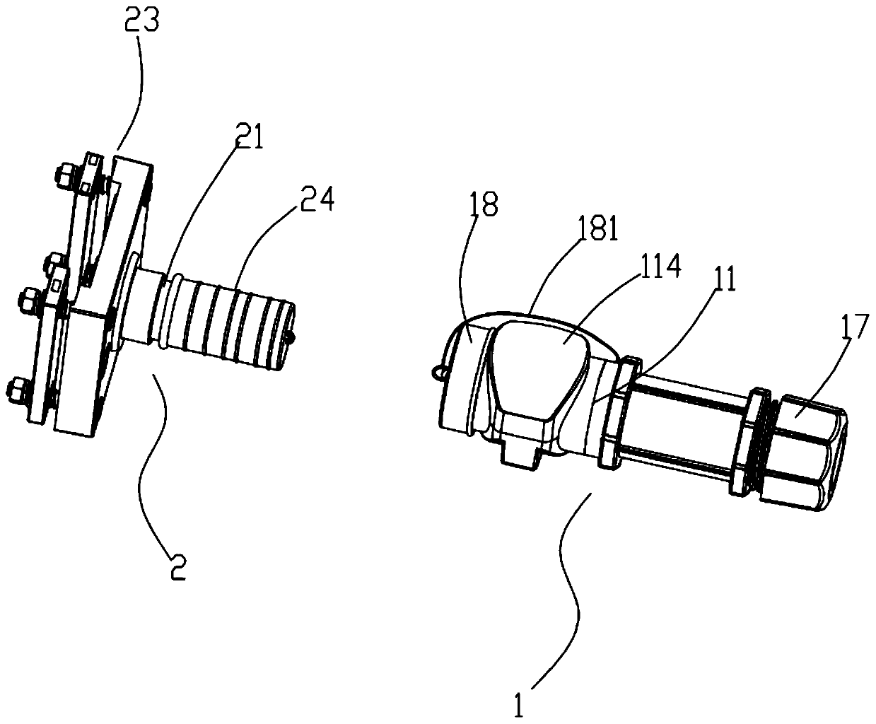
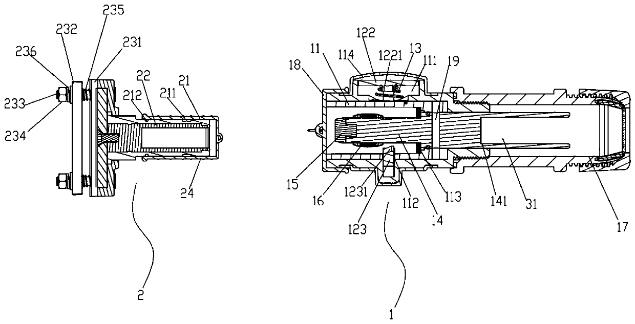
[0030] Such as Figure 1-5 As shown, the push-in connector seat includes a female plug 1 and a male plug 2. The female plug 1 includes an insulating sleeve 11, a conductive finger 14 and a locking key 12. The locking key 12 is a ring structure, including a ring The main body 121 and the pressing part 122 and the latch 123 arranged on opposite sides of the annular body 121, the outer wall of the insertion sleeve 11 is provided with an accommodating groove 111 for guiding the locking key 12, and the locking key 12 is sleeved on the insertion sleeve The barrel 11 is placed outside the housing groove 111, and a pre-tension spring 13 is provided between the pressing part 122 and the outer wall of the socket sleeve 11, and a pin hole 112 is provided on the socket sleeve 11 facing the pin 123. The elastic force of the pre-tension spring 13 enables the end of the plug pin 123 to be inserted into the inner cavity of the socket sleeve 11 through the pin hole 112. There is a wedge-shape...

Embodiment 2

[0040] On the basis of the technical solution of embodiment 1, the conductive positioning mechanism has been changed:

[0041] Such as Figure 6 As shown, the conductive positioning mechanism is a connection terminal 237, one end of the connection terminal 237 is fixedly connected to the conductive cylinder 22, and the other end is provided with a mounting hole 2371 for fixing and connecting the conductor through screws. Compared with the elastic clip seat 23, this structure has a simpler structure and is more convenient to use, although the scope of use is smaller.


PUM


Abstract

The invention relates to the field of electric power tools, in particular to a quick-plug connector seat. The connector seat comprises a female plug and a male plug. The female plug comprises a plug sleeve, a conductive plug finger, a lock key and a wiring mechanism, the lock key is provided with a pressing part and a plug pin which are oppositely arranged, the lock key sleeves the outside of theplug sleeve, a pre-tightening spring is arranged between the pressing part and the outer side wall of the plug sleeve, a pin hole is formed in the plug sleeve opposite to the plug pin, and the end part of the plug pin is of a one-way non-return tooth structure. The male plug comprises a connecting plug and a conductive positioning mechanism. An annular groove is formed in the outer side wall of the connecting plug, a conductive cylinder is arranged on the inner side wall of the connecting plug, the connecting plug can eject the plug pin open to enable the connecting plug to be inserted smoothly when inserted into the plug sleeve in the forward direction, the plug pin can be inserted into the annular groove, and therefore the connecting plug cannot retreat from the plug sleeve reversely butcan rotate relative to the plug sleeve. According to the invention, the quick connection of the male plug and the female plug can be realized, the operation is convenient, the connection is firm, themale plug and the female plug can rotate freely in a connected state, and the use is flexible.

Description

technical field [0001] The invention relates to the field of electric tools, in particular to a quick-plug connector seat. Background technique [0002] The quick-plug connector seat is generally used for fixing and conductively connecting the cable wires with the conductors that need to be wired (such as the terminal block in the distribution box). To connect, you need to adjust the angle of the male plug and the female plug first so that the position of the hanging pin is opposite to the hanging slot, and then insert the male plug into the female plug and rotate a certain angle so that the hanging pin is embedded in the hanging slot, so as to realize Snap connection of male and female plugs. This connection method has the following problems: it is inconvenient to operate, and the angle between the male plug and the female plug needs to be adjusted before the male plug can be inserted into the female plug; after the male plug and the female plug are connected, the male plu...

Claims


Application Information

Patent Timeline
Patent Type & Authority Applications(China)
IPC IPC(8): H01R13/17H01R13/502H01R13/52H01R13/59H01R13/627H01R13/633H01R13/64H01R24/00H01R4/46H01R4/48H01R24/38
CPCH01R4/46H01R4/4863H01R13/17H01R13/502H01R13/5202H01R13/5205H01R13/5219H01R13/59H01R13/6278H01R13/6335H01R13/64H01R24/005H01R24/38
Inventor 胡超强邹科敏尤占山邵源鹏高伟光许翠珊冯泽华徐秋燕王骞能胡玉莹陈雪儿刘金勇陈匡迪郝燕冯家杰
Owner GUANGZHOU PANYU CABLE WORKS
Why Eureka
Try Eureka