Hall sensor

A Hall sensor and sensor body technology, applied in the field of sensors, can solve the problems of inconvenient maintenance or replacement of Hall sensors, and difficulty in fully guaranteeing the stability of Hall sensors, and achieve the effects of improving stability, suppressing abnormal heat, and avoiding damage.

Pending Publication Date: 2022-04-12
陈伟明
View PDF0 Cites 0 Cited by
  • Summary
  • Abstract
  • Description
  • Claims
  • Application Information

AI Technical Summary

Problems solved by technology

[0003] However, there are certain defects in the existing Hall sensors: in actual installation, Hall sensors are mostly fixed by pin welding or by screws, and the installation of the board by screws has certain requirements, and conventional screws are difficult to fully guarantee The stability of the installation of the Hall sensor is not easy to repair or replace the damaged Hall sensor

Method used


Image

  • Hall sensor
  • Hall sensor
  • Hall sensor

Examples


Embodiment Construction

[0036] The following will clearly and completely describe the technical solutions in the embodiments of the present invention with reference to the accompanying drawings in the embodiments of the present invention. Obviously, the described embodiments are only some, not all, embodiments of the present invention. Based on the embodiments of the present invention, all other embodiments obtained by persons of ordinary skill in the art without making creative efforts belong to the protection scope of the present invention.

[0037] In describing the present invention, it is to be understood that the terms "center", "longitudinal", "transverse", "length", "width", "thickness", "upper", "lower", "front", " Back", "Left", "Right", "Straight", "Horizontal", "Top", "Bottom", "Inner", "Outer", "Clockwise", "Counterclockwise", etc. or The positional relationship is based on the orientation or positional relationship shown in the drawings, which is only for the convenience of describing t...


PUM


Abstract

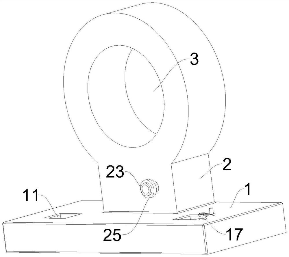
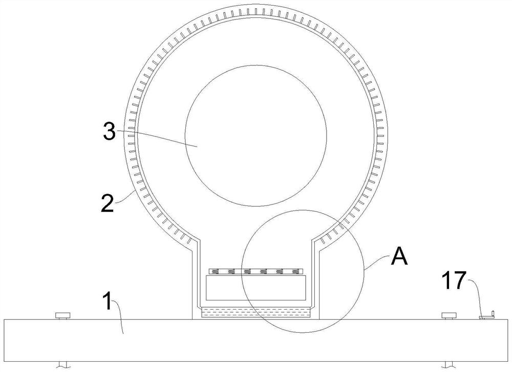
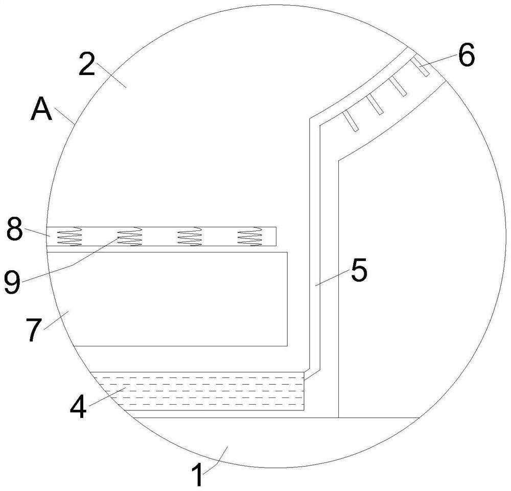
The invention relates to the technical field of sensors, in particular to a Hall sensor which comprises a bottom plate, a sensor body fixedly installed at the upper end of the bottom plate and studs used for fixing the bottom plate, a threading hole is formed in the sensor body, and two rectangular openings matched with the studs are symmetrically formed in the upper end of the bottom plate. Grooves communicating with the rectangular opening are further formed in the bottom plate, and clamping plates are installed in the two grooves in a sliding mode. According to the invention, clamping of the stud is maintained through worm and gear transmission, the stability of the sensor body after fixation is improved, and power is supplied to a plurality of solenoid coils in the strip-shaped cavity, so that abnormal heating of electrical elements in the equipment cavity is inhibited, the sensor body is prevented from being damaged due to overheating, and the reliability of the sensor body is improved. And evaporated liquid in the liquid storage cavity is heated and gasified, and then heat dissipation is continuously conducted on the interior of the equipment cavity.

Description

technical field [0001] The invention relates to the technical field of sensors, in particular to a Hall sensor. Background technique [0002] The Hall effect is a kind of electromagnetic effect. This phenomenon was discovered by the American physicist Hall in 1879 when he was studying the conductive mechanism of metals. When the current passes through the semiconductor perpendicular to the external magnetic field, the carriers are deflected, and the vertical An additional electric field will be generated in the direction of the current and magnetic field, thereby generating a potential difference at both ends of the semiconductor. This phenomenon is the Hall effect, and this potential difference is also called the Hall potential difference. The Hall current sensor is based on the magnetic balance Hall principle. According to the Hall effect principle, the current Ic is passed through the control current terminal of the Hall element, and a magnetic field with a magnetic induc...

Claims


Application Information

Patent Timeline
IPC IPC(8): G01D5/14G01D11/00
Inventor 陈伟明李澳
Owner 陈伟明
Why Eureka
Try Eureka