Scanner rib structure, scanner, multifunction machine

A scanner and structure technology, applied in the field of scanners, can solve the problems of original document edge warping, damage, hindering the normal removal of the original document, etc.

Active Publication Date: 2020-09-01
至像科技有限公司
View PDF6 Cites 0 Cited by
  • Summary
  • Abstract
  • Description
  • Claims
  • Application Information

AI Technical Summary

Problems solved by technology

[0003] like figure 1 and 2 As shown, it is an existing structure of an original document carrier. In this structure, the upper cover 1 is formed with overlapping edges 4 pressed on the scanning glass 2 along the surrounding edges of the scanning glass 2, so as to realize the scanning glass 2, The upper cover 1 and the lower cover (not shown) are snapped together to form an airtight scanning space. However, as we all know, the scanner has ADF scanning and FB scanning. The original is removed from the scanning glass 2, figure 1 As shown in , due to the overlapping edge 4, there is a gap formed between the front end of the overlapping edge 4 and the upper surface of the scanning glass 2. The above gap will hinder the normal removal of the original, and even the original will be damaged when the user uses too much force. Obstructed edge warping or breakage
[0004] image 3 Based on the above problems, the shown structure of the original loading platform has been improved accordingly. It removes the overlapping edge structure in the direction of the original taking out, and correspondingly processes the receiving platform on the lower cover 3 to ensure the fixed installation of the scanning glass. However, the above The scheme will cause a gap between the original platen 5 and the upper end of the lower cover 3, and the light and dust from the outside will pass through the gap and enter the scanning optical components, affecting the quality of scanning.

Method used


Image

  • Scanner rib structure, scanner, multifunction machine
  • Scanner rib structure, scanner, multifunction machine
  • Scanner rib structure, scanner, multifunction machine

Examples


Embodiment 1

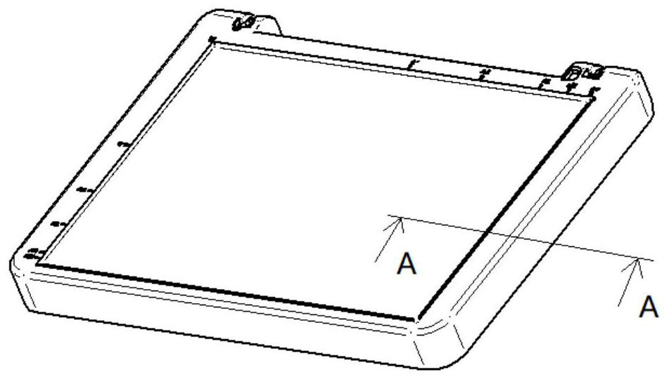
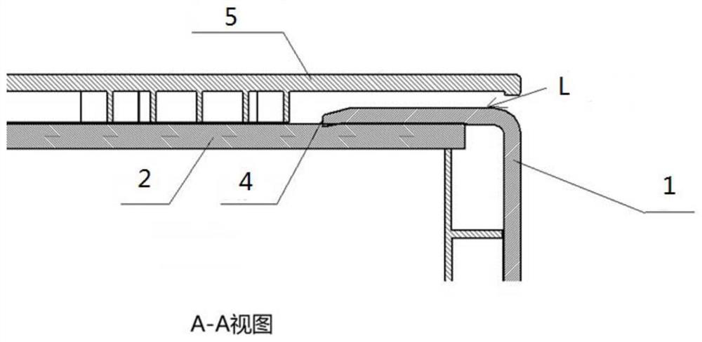
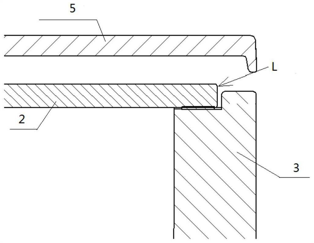
[0048] Such as Figure 4 to Figure 8 As shown, a sidewall structure for a scanner provided in this embodiment includes an upper cover 1, a lower cover 2, a scanning glass 3 and an original platen 4, and the lower cover 2 is formed with a protruding scanning glass corresponding to the side where the original is taken out. 3 the sealing part 21 provided on the upper surface, the sealing part 21 has a guide surface 211 provided adjacent to the outer edge of the scanning glass 3 and a sealing surface 212 which cooperates with the original pressing plate 4 to form a unilateral seal. In this embodiment, a sealing surface 212 cooperating with the original pressing plate 4 is provided to prevent external dust and light from entering the scanner to ensure scanning quality. A guiding surface 211 is provided to facilitate the sliding of the original from the guiding surface 211.

[0049] The upper cover 1 and the lower cover 2 in this embodiment are both injection molded parts, and their...

Embodiment 2

[0064] This embodiment provides a scanner, which includes the sidewall structure for a scanner described in Embodiment 1 above, and has all its technical advantages, which will not be repeated here.

Embodiment 3

[0066] This embodiment provides a multifunctional machine, including the scanner in Embodiment 2.

[0067] During specific implementation, the scanner in Embodiment 2 is generally installed on a matching printer to form a multifunctional machine structurally.


PUM


Abstract

The invention provides a flange structure for a scanner, the scanner and a multifunctional machine. The flange structure for the scanner comprises an upper cover, a lower cover, scanning glass and anoriginal manuscript pressing plate, a sealing part which at least partially protrudes out of the upper surface of the scanning glass is formed on the side, corresponding to the manuscript taking-out side, of the lower cover, and the sealing part is provided with a guide surface adjacent to the outer edge of the scanning glass and a sealing surface which is matched with the manuscript pressing plate to form single-side sealing. According to the scanner, the sealing surface matched with the manuscript pressing plate is arranged to prevent external dust and light from entering the scanner, so that the scanning quality is guaranteed, and the manuscript can conveniently slide out of the guide surface due to the arrangement of the guide surface.

Description

technical field [0001] The invention relates to the technical field of scanners, in particular to a sidewall structure for scanners, a scanner and a multifunctional machine. Background technique [0002] The document reading stage of the scanner in the prior art generally consists of four parts, an upper cover, a lower cover, a document pressing plate and glass, to form a frame structure. [0003] Such as figure 1 and 2 As shown, it is an existing structure of an original document carrier. In this structure, the upper cover 1 is formed with overlapping edges 4 pressed on the scanning glass 2 along the surrounding edges of the scanning glass 2, so as to realize the scanning glass 2, The upper cover 1 and the lower cover (not shown) are snapped together to form an airtight scanning space. However, as we all know, the scanner has ADF scanning and FB scanning. The original is removed from the scanning glass 2, figure 1 As shown in , due to the overlapping edge 4, there is a ...

Claims


Application Information

Patent Timeline
Patent Type & Authority Patents(China)
IPC IPC(8): H04N1/00H04N1/04
CPCH04N1/00474H04N1/00519H04N1/00551H04N1/00567H04N1/04
Inventor 唐波炯姜乔范志国
Owner 至像科技有限公司
Why Eureka
Try Eureka