
Positioning mechanism of engraving and milling machine

A positioning mechanism, engraving and milling machine technology, used in multi-purpose machinery, forming/shaping machines, special forming/shaping machines, etc., can solve the problem of low positioning accuracy, improve positioning ability, ensure positioning ability, increase positioning range effect

Pending Publication Date: 2019-11-26
吴善旺
View PDF3 Cites 0 Cited by
  • Summary
  • Abstract
  • Description
  • Claims
  • Application Information

AI Technical Summary

Problems solved by technology

[0004] The purpose of the present invention is to solve the above-mentioned problems in the existing technology, and propose a positioning mechanism for engraving and milling machines to solve the problem of low positioning accuracy of existing engraving and milling machines for wood

Method used


Image

  • Positioning mechanism of engraving and milling machine
  • Positioning mechanism of engraving and milling machine
  • Positioning mechanism of engraving and milling machine

Examples


Embodiment 1

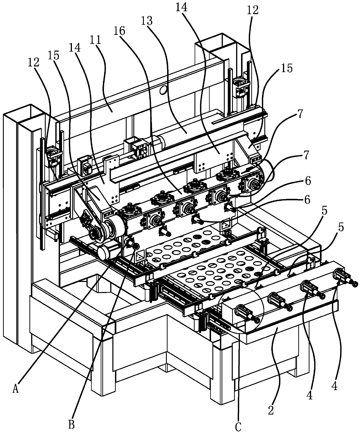
[0029] Such as figure 1 As shown, the positioning mechanism of the engraving and milling machine, the engraving and milling machine includes a frame 1, and the frame 1 is provided with a gantry 11, and the two columns of the gantry 11 are vertically slidably connected with a vertical carriage 12, and the two vertical carriages 12 A crossbeam 13 is fixed horizontally between them, on the crossbeam 13, a horizontal carriage 14 is slidably connected in the transverse direction, and two supports 15 are fixed on the transverse carriage 14, and a strip-shaped tool holder 16 is rotatably connected between the two supports 15 , the tool holder 16 is arranged horizontally, on the tool holder 16 there are multiple groups of processing components 7 along the horizontal direction, the processing components 7 are processing motors, cutter heads, milling heads, etc., and a processing platform is also slidingly connected longitudinally on the frame 1 2. The vertical carriage 12, the horizont...

Embodiment 2

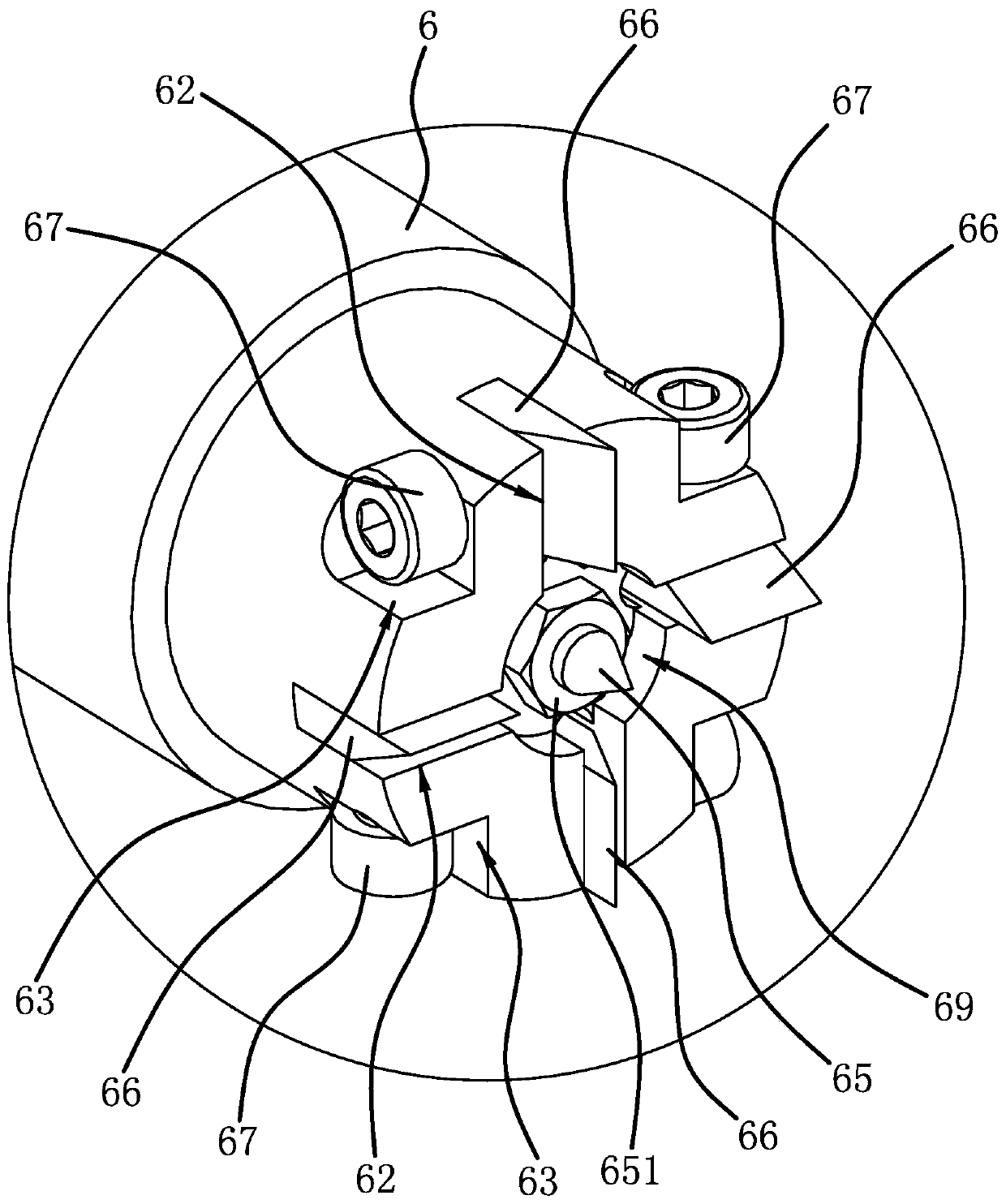
[0033] The positioning mechanism of the engraving and milling machine is basically the same as that of the first embodiment, except that the positioning column 65 and the rotating shaft 6 are integrally structured to increase the structural strength and stability of the positioning column 65 .


PUM


Abstract

The invention provides a positioning mechanism of an engraving and milling machine and belongs to the technical field of mechanical machining equipment. The positioning mechanism solves the problem that an existing engraving and milling machine is low in wood positioning precision. The positioning mechanism of the engraving and milling machine comprises centres and rotary shafts opposite to the centres. A positioning column with one end in a pointed shape is fixed to the end of each rotary shaft in the axial direction, wherein the pointed end of the positioning column protrudes out of the endsurface of the rotary shaft. A plurality of insert grooves are formed in the end surface of each rotary shaft. Positioning plates are inserted into the insert grooves in a sliding mode in the axial direction of the rotary shafts and protrude out of the end surfaces of the rotary shafts. The positioning plates are locked and fixed into the insert grooves through fasteners, and the fasteners are detachably connected with the rotary shafts correspondingly. By means of the positioning mechanism of the engraving and milling machine, the wood positioning precision can be improved.

Description

technical field [0001] The invention belongs to the technical field of mechanical processing equipment, and relates to a positioning mechanism of an engraving and milling machine. Background technique [0002] Engraving and milling machine is a kind of CNC machine tool, which can be used for both engraving and milling. It is a high-efficiency and high-precision CNC machine tool with a wide range of applications. Engraving and milling machines for processing wood of different shapes are usually equipped with different positioning Mechanisms, especially for columnar wood, and the wood needs to be rotated to cooperate with the processing during the processing. The positioning mechanism must not only realize the positioning of the wood, but also realize the rotation of the wood. The patent document (application number: 201410114189.7) discloses a control four The shaft engraving machine includes a frame, screw rods are arranged on both sides of the frame, the beam is set on the ...

Claims


Application Information

Patent Timeline
IPC IPC(8): B27C5/02B27C5/06B27C9/04
CPCB27C5/02B27C5/06B27C9/04
Inventor 吴善旺
Owner 吴善旺
Features
  • Generate Ideas
  • Intellectual Property
  • Life Sciences
  • Materials
  • Tech Scout
  • Unparalleled Data Quality
  • Higher Quality Content
  • 60% Fewer Hallucinations
Learn More