
A grating signal compensation method and compensation system

A technology of grating signal and compensation method, applied in the direction of using optical devices, instruments, measuring devices, etc., can solve the problems of cumbersome tabulation process, poor flexibility of look-up table subdivision method, and increase of look-up tables, etc., to save on-chip resources , save the tedious work, improve the effect of flexibility

Active Publication Date: 2021-02-12
GUANGDONG UNIV OF TECH
View PDF5 Cites 0 Cited by
  • Summary
  • Abstract
  • Description
  • Claims
  • Application Information

AI Technical Summary

Problems solved by technology

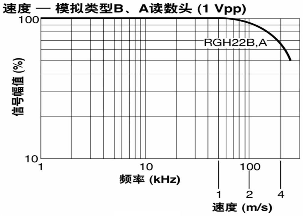
[0005] However, when collecting grating signals, in order to achieve the purpose of precise displacement measurement, a higher-precision ADC should be used; with the improvement of ADC precision, the range of amplitude variation of signal attenuation will be larger, and the required look-up table The number will also increase
Making corresponding lookup tables according to different attenuation conditions not only requires a cumbersome and repetitive tabulation process, but also when the accuracy of the ADC changes, the existing lookup tables are no longer applicable and need to be re-made to make the lookup table subdivided The method is less flexible

Method used


Image

  • A grating signal compensation method and compensation system
  • A grating signal compensation method and compensation system
  • A grating signal compensation method and compensation system

Examples


Embodiment 1

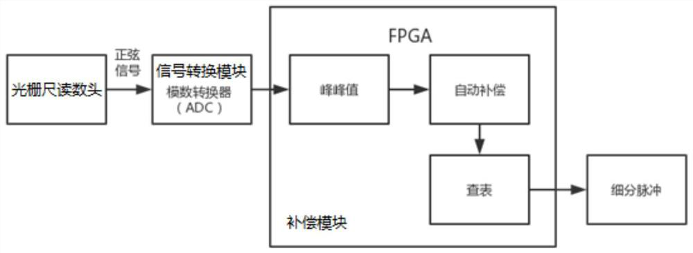
[0051] This embodiment provides a method for compensating grating signals based on FPGA, comprising the following steps:

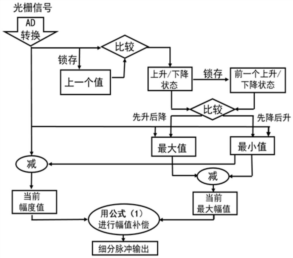
[0052] The sinusoidal grating electrical signal output by the grating scale is converted into a digital signal by an 8-bit ADC and input to the FPGA, and automatically compensated according to formula 1 in the FPGA, and the compensated value is used as the address look-up table to output the subdivision pulse. The specific simulation The result is as Figure 5 shown.

[0053] Embodiment effect:

[0054] The output of the subdivision pulse is determined according to the range of the amplitude after compensation. Combining with the simulation, it can be seen that the amplitude after compensation by this method can meet the requirements of subsequent subdivision. Assuming that the signal is attenuated to 50% of the maximum peak-to-peak value, the peak-to-peak dynamic range of the corresponding 8-bit analog-to-digital converter is 255-128, that is, 128 diffe...


PUM


Abstract

The invention discloses a grating signal compensation method and compensation system. The compensation method includes: collecting a grating signal outputted by a grating ruler and performing digital-to-analog conversion to obtain a digital signal; making a look-up table according to the digital-to-analog conversion accuracy; with a cycle as a unit, determining an amplitude status of the signal, acquiring maximum and minimum values of the amplitude, and calculating a peak-to-peak value of the signal; and compensating the amplitude by using the peak-to-peak and the minimum value of the amplitude, inquiring the look-up table by using the compensate amplitude as an address, and outputting a subdivision pulse. According to the invention, the look-up table is made based on the numerical range outputted by the analog-to-digital converter; the amplitude of the attenuated sinusoidal electrical signal is automatically compensated, so that the compensated amplitude value is suitable for thesame look-up table; and look-up table subdivision is carried out based on the compensated amplitude value. Therefore, the tedious work of making lots of look-up tables is saved and the flexibility oflook-up table subdivision is improved; and thus problems of poor flexibility and high storage resource consumption of existing lookup table methods are solved.

Description

technical field [0001] The invention relates to the field of grating signal processing, in particular to a grating signal compensation method and compensation system. Background technique [0002] At present, as a precise displacement measurement tool, the grating ruler is widely used in displacement measurement in the manufacturing industry. The use of gratings to measure displacement is based on the moiré fringe signal. During the relative motion of the grating, the moiré fringe signal is photoelectrically converted into a periodically changing sinusoidal electrical signal. The sinusoidal signal is digitally subdivided and then transmitted to the subsequent electronic circuit to achieve The purpose of precision displacement measurement. [0003] Subdivision methods include hardware subdivision and software subdivision. The hardware subdivision method uses multiple comparators to subdivide the signal. When the subdivision multiple is large, the hardware circuit is very co...

Claims


Application Information

Patent Timeline
Patent Type & Authority Patents(China)
IPC IPC(8): G01B11/02
CPCG01B11/02
Inventor 李俊颖杨志军吴建成
Owner GUANGDONG UNIV OF TECH
Learn More