
A Method for Controlling the Error of Beam Bridge Deflection Test

An error control and beam bridge technology, applied in measuring devices, complex mathematical operations, instruments, etc., can solve problems such as system errors and test system errors, achieve the effect of eliminating system errors and improving the accuracy of deflection measurement

Active Publication Date: 2021-04-20
ZHENGZHOU UNIV
View PDF6 Cites 0 Cited by
  • Summary
  • Abstract
  • Description
  • Claims
  • Application Information

AI Technical Summary

Problems solved by technology

In reality, the beam body at the observation point has a certain inclination with the overall deformation of the bridge. At this moment, the value observed horizontally at the same position is different from the actual situation, and the system error is caused by this.
[0005] Similarly, for continuous girder bridges, when a span is loaded, the girder bodies of each span will have different implicated deformations, and placing the instrument on the girder body will also cause systematic errors in the test. Therefore, for simply supported beams and continuous girders For the deflection test, there are systematic errors caused by the defects of the test method

Method used


Image

  • A Method for Controlling the Error of Beam Bridge Deflection Test
  • A Method for Controlling the Error of Beam Bridge Deflection Test
  • A Method for Controlling the Error of Beam Bridge Deflection Test

Examples


Embodiment 1

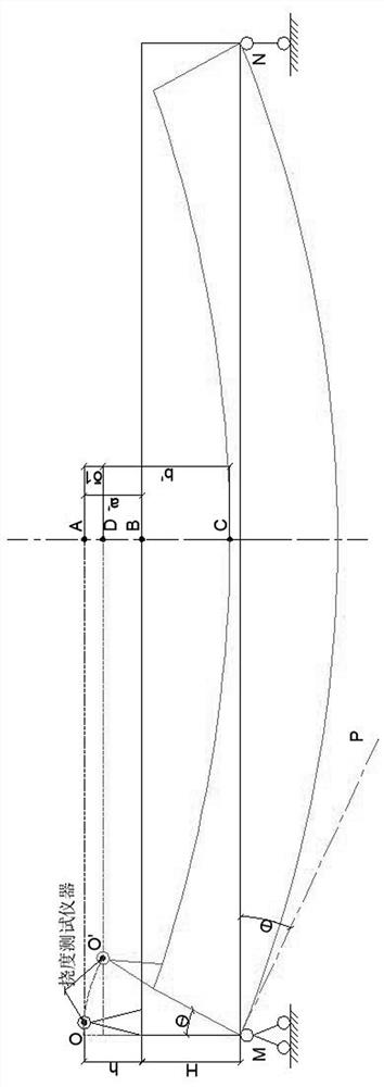
[0102] Such as figure 1 As shown, the traditional deflection test does not consider the deformation of the beam body, that is, the displacement of the instrument with the deformation of the beam is not considered. After the beam is deformed, the deflection testing instrument tilts and changes the height of the lens, thereby changing the intersection of the line of sight and the central axis of the mid-span position. Therefore, this embodiment removes the implicated displacement deviation caused by the tilt of the deflection testing instrument when calculating the deflection value.

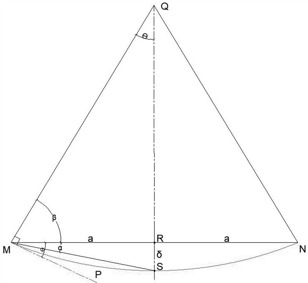
[0103] For simply supported beams, when testing the mid-span deflection, when the instrument is placed on the support, the line of sight of the deflection testing instrument telescope is point O, and the intersection of the horizontal line of sight and the central axis of the mid-span position is A. The mid-span position is B, then in the case of no load, the measured elevation of the mid-span posi...

Embodiment 2

[0134] The difference between this embodiment and the first embodiment is that when the instrument is placed on the support, the line of sight is not adjusted when the instrument deforms with the beam body.

[0135] After the beam body is deformed, the line of sight direction of the deflection testing instrument is tilted with the rotation of the support. This embodiment removes the implicated displacement deviation caused by the tilt of the deflection testing instrument and the line of sight displacement deviation caused by the tilt of the deflection testing instrument when calculating the deflection value.

[0136] For simply supported beams, when the instrument is placed at the support to test the mid-span deflection, before loading, the line of sight of the deflection test instrument telescope is point O, and the intersection point of the horizontal line of sight and the central axis of the mid-span position is A. The mid-span position of the body is B, and the elevation of...

Embodiment 3

[0160] In the actual test process, when the span is large, the instrument cannot be placed at the support, but placed between the support and the mid-span, such as Figure 5 As shown, the actual deflection value at this moment needs to be calculated separately; this embodiment removes the implicated displacement deviation caused by the inclination of the deflection testing instrument and the distance deviation between the deflection testing instrument and the support when calculating the deflection value. In this embodiment, when the instrument is tilted, the instrument is manually adjusted so that the line of sight is horizontal.

[0161] In the case of adjusting the line of sight of the instrument to the horizontal after loading, before loading, the line of sight of the deflection testing instrument telescope is point O, the intersection of the horizontal line of sight and the central axis of the mid-span position is A, and the mid-span position of the beam body is B. The el...


PUM


Abstract

The invention discloses a deflection test error control method of a girder bridge. First, no load is applied to the bridge, and the initial distance parameter between the deflection test instrument and the central axis of the bridge mid-span is collected; then, the load is loaded on the bridge mid-span, and the deflection is collected Test the deformed distance parameters between the instrument and the central axis of the bridge mid-span position, calculate the deflection value, and finally remove the deflection value deviation. The invention calculates the size of the implicated displacement and the line-of-sight displacement through the revised formula, eliminates the implicated displacement deviation and the line-of-sight displacement deviation caused by the deflection measuring instrument tilting with the beam body during the deflection measurement process, and then obtains the true value of the support rotation angle and the deflection of the measuring point, and improves The accuracy of deflection measurement can eliminate systematic errors and ensure the stability and reliability of bridge measurement results.

Description

technical field [0001] The invention relates to the technical field of bridges, in particular to a method for controlling deflection test errors of girder bridges. Background technique [0002] Generally, when deflection testing is performed on bridges, levels or other deflection testing instruments are usually used for measurement. Generally speaking, the "Engineering Survey Specifications" stipulates that the length of the line of sight of the second-class leveling observation should not exceed 50m, and the distance of the front and rear sight should not exceed 25m; the length of the line of sight of the fourth-class leveling observation should not exceed 100m, and the distance of the front and rear sight should not exceed 50m. . Within the line of sight stipulated in the code, the accuracy of the level is relatively high, and if it exceeds this test range, large errors will occur, which will lead to invalidation of the deflection test results. [0003] For simply suppor...

Claims


Application Information

Patent Timeline
Patent Type & Authority Patents(China)
IPC IPC(8): G01B21/32G06F17/10
CPCG01B21/32G06F17/10
Inventor 梁岩时晓晔时照东赵博洋周瑞娇闫晗菲陈淮
Owner ZHENGZHOU UNIV
Learn More