optical lens

An optical lens and lens technology, applied in the field of optical lenses, can solve the problems of enlarged CRA, large aperture, and small field of view, and achieve the effect of back focal length and large distortion

Active Publication Date: 2022-01-14
NINGBO SUNNY AUTOMOTIVE OPTECH
View PDF4 Cites 0 Cited by
  • Summary
  • Abstract
  • Description
  • Claims
  • Application Information

AI Technical Summary

Problems solved by technology

[0003] However, as the resolution increases, the volume and weight of the corresponding lens will increase, and the contradiction between lens resolution and miniaturization becomes increasingly prominent. The conventional front-view vehicle lens has a large front port diameter, a small angle, and a small field of view. If the overall length is shortened, the back focus of the whole system will become smaller, resulting in larger CRA, which cannot perfectly match the chip, and is not conducive to actual installation
At present, vehicular optical lenses with more than one million pixels usually use 6 lenses. Although the resolution is significantly improved compared with 5 lenses, the increase in the number of lenses makes it more difficult to miniaturize the lens. For lenses that work in harsh environments and have limited installation space, on the basis of ensuring the stability in different working environments, further improving the direction of miniaturization and high resolution has become the mainstream trend of vehicle lens development

Method used


Image

  • optical lens
  • optical lens
  • optical lens

Examples


Embodiment 1

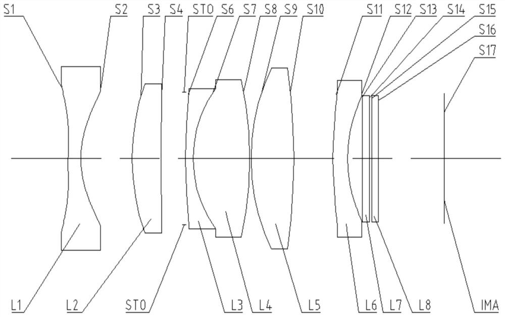
[0070] Refer to the following figure 1 An optical lens according to Embodiment 1 of the present application is described. figure 1 A schematic structural diagram of the optical lens according to Embodiment 1 of the present application is shown.

[0071] Such as figure 1 As shown, the optical lens sequentially includes a first lens L1 , a second lens L2 , a third lens L3 , a fourth lens L4 , a fifth lens L5 and a sixth lens L6 along the optical axis from the object side to the imaging side.

[0072] The first lens L1 is a meniscus lens with negative refractive power, the object side S1 is convex, and the image side S2 is concave. In addition, the first lens L1 is an aspherical lens, and its object side S1 and image side S2 are both aspherical.

[0073] The second lens L2 is a biconvex lens with positive refractive power, and its object side S3 and image side S4 are both convex.

[0074] The third lens L3 is a biconcave lens with negative refractive power, and its object sid...

Embodiment 2

[0093] Refer to the following figure 2 An optical lens according to Embodiment 2 of the present application is described. In this embodiment and the following embodiments, for the sake of brevity, descriptions similar to those in Embodiment 1 will be omitted. figure 2 A schematic structural view of the optical lens according to Embodiment 2 of the present application is shown.

[0094] Such as figure 2 As shown, the optical lens sequentially includes a first lens L1 , a second lens L2 , a third lens L3 , a fourth lens L4 , a fifth lens L5 and a sixth lens L6 along the optical axis from the object side to the imaging side.

[0095] The first lens L1 is a meniscus lens with negative refractive power, the object side S1 is convex, and the image side S2 is concave. In addition, the first lens L1 is an aspherical lens, and its object side S1 and image side S2 are both aspherical.

[0096] The second lens L2 is a meniscus lens with positive refractive power, the object side S...

Embodiment 3

[0111] Refer to the following image 3 An optical lens according to Embodiment 3 of the present application is described. In this embodiment and the following embodiments, for the sake of brevity, descriptions similar to those in Embodiment 1 will be omitted. image 3 A schematic structural diagram of an optical lens according to Embodiment 3 of the present application is shown.

[0112] Such as image 3 As shown, the optical lens sequentially includes a first lens L1 , a second lens L2 , a third lens L3 , a fourth lens L4 , a fifth lens L5 and a sixth lens L6 along the optical axis from the object side to the imaging side.

[0113] The first lens L1 is a meniscus lens with negative refractive power, the object side S1 is convex, and the image side S2 is concave. In addition, the first lens L1 is an aspherical lens, and its object side S1 and image side S2 are both aspherical.

[0114] The second lens L2 is a biconvex lens with positive refractive power, and its object sid...


PUM


Abstract

The present application discloses an optical lens, and the optical lens may include sequentially from the object side to the image side along the optical axis: a first lens, a second lens, a third lens, a fourth lens, a fifth lens, and a sixth lens. lens. Wherein, the first lens can have negative refractive power, and its object side is convex, and the image side is concave; the second lens can have positive refractive power, and its object side is convex; the fifth lens can have positive refractive power, and its object side and the image side are both convex; the sixth lens can have negative refractive power, and its image side is concave; and the third lens and the fourth lens can be glued together to form a cemented lens. According to the optical lens of the present application, at least one beneficial effect of high resolution, miniaturization, small diameter at the front end, telephoto, large field of view, small chief ray angle, and back focal length can be realized.

Description

technical field [0001] The present application relates to an optical lens, and more particularly, the present application relates to an optical lens including six lenses. Background technique [0002] As the "eyes" of the car, the vehicle lens plays a very important role in the vehicle assisted driving system. With the rapid development of technology, people's requirements for the vehicle lens are getting higher and higher. High resolution, miniaturization, and stability in different working environments have always been the technical bottlenecks of vehicle-mounted lenses. At present, the popularization and application of vehicle-mounted lenses has made people have higher and higher requirements for the resolution of vehicle-mounted lenses. From the original megapixels, Continuously improve the popularity in the direction of 2M. [0003] However, as the resolution increases, the volume and weight of the corresponding lens will increase, and the contradiction between lens re...

Claims


Application Information

Patent Timeline
Patent Type & Authority Patents(China)
IPC IPC(8): G02B13/18G02B13/06
CPCG02B13/006G02B13/0045G02B13/06
Inventor 王东方孙毅姚波
Owner NINGBO SUNNY AUTOMOTIVE OPTECH
Why Eureka
Try Eureka