Ultrasonic flow meter

A flow measuring device and component technology, which is applied in measuring devices, measuring flow/mass flow, liquid/fluid solid measurement, etc., can solve problems such as unsuitable flow velocity

Active Publication Date: 2019-11-26
SIEMENS SWITZERLAND
View PDF11 Cites 0 Cited by
  • Summary
  • Abstract
  • Description
  • Claims
  • Application Information

AI Technical Summary

Problems solved by technology

The sensor is not suitable for determining the flow velocity of the medium flowing in the pipeline

Method used


Image

  • Ultrasonic flow meter
  • Ultrasonic flow meter
  • Ultrasonic flow meter

Examples


Embodiment Construction

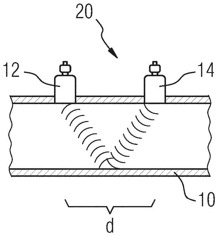
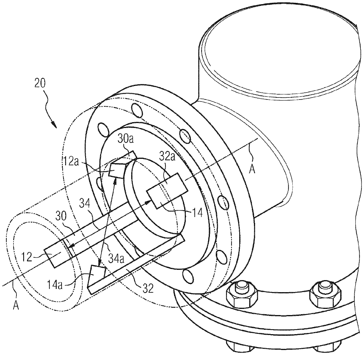
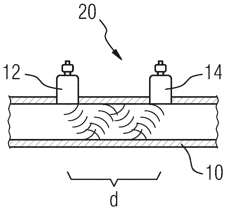
[0023] The measurement of the flow velocity of the medium in line 10 by means of ultrasound is known per se. The diagrammatic simplifications of FIGS. 1 , 2 and 3 show different configurations. A sensor pair is then assigned to the line 10 through which the medium flows, the flow velocity of which is to be ascertained. The sensor pair comprises a first ultrasonic sensor 12 and a second ultrasonic sensor 14 . The two ultrasonic sensors 12 , 14 , sometimes referred to below as sensors 12 , 14 for short and collectively as sensors 12 , 14 , operate as ultrasonic transmitters and ultrasonic receivers. The sensors 12 , 14 are arranged at a distance from one another in the flow direction of the medium flowing through the line 10 , ie in the axial direction of the line 10 .

[0024] Both sensors 12 , 14 function together as a flow measuring device 20 . The sensor signals of the sensors 12, 14 are evaluated by means of an evaluation device 22 belonging to the flow measuring device ...


PUM


Abstract

The invention relates to flow meter (20) having at least two sensors (12, 14; 12a, 14a) which are arranged at a distance from one another, wherein said flow meter does not comprise any measuring tubewhich is otherwise necessary in many cases, wherein the sensors are located in each case at a free end of an extension (30, 32; 30a, 32a) extending from a ring-shaped carrier part (24) that is intended for mounting to a flange surface of a tube section. The flow meter can be placed between two tube segments (26, 28) of a conduit (10) by means of the ring-shaped carrier part. The extensions are aligned perpendicularly or at least substantially perpendicularly to a plane defined by the carrier part. Two sensors define in each case a signal path (34, 34a), and the signal path comprises a component (38) perpendicular to the plane defined by the carrier part. Among the exactly four sensors and correspondingly four extensions, two sensors in particular form in each case a sensor pair and the extensions carrying them form an extension pair, wherein, in each extension pair, either each extension points into another direction starting from the carrier part or, in the case of extensions orientedin the same direction, the extensions are of different lengths.

Description

technical field [0001] The invention relates to a flow measuring device, ie a flow measuring device intended to output measured values ​​encoding the flow velocity of a medium flowing through a line. Background technique [0002] Such flow measuring devices are known per se. For example, two ultrasonic sensors spaced apart in the axial direction of the measuring tube are located in a measuring tube. In the medium flowing through the measuring tube, the ultrasonic signals emitted by one of the two ultrasonic sensors in the direction of the other ultrasonic sensor propagate at least partially in the flow direction of the medium, and the ultrasonic signals emitted in the opposite direction correspondingly at least partially reverse propagating in the direction of flow of the medium. By determining the propagation time difference between an ultrasonic signal propagating in the direction of flow of the medium and an ultrasonic signal propagating against the direction of flow of...

Claims


Application Information

Patent Timeline
Patent Type & Authority Applications(China)
IPC IPC(8): G01F1/66
CPCG01F1/662G01F15/18G01F15/185
Inventor P.亨茨曼T.西格里斯特
Owner SIEMENS SWITZERLAND
Why Eureka
Try Eureka