Optical film for eyewear with light-blocking function, optical laminate using same and eyewear with light-blocking function
An optical film and optical layer technology, applied in optics, optical components, optical components, etc., can solve problems such as darkening of the field of view, and achieve the effect of superior fashion
- Summary
- Abstract
- Description
- Claims
- Application Information
AI Technical Summary
Problems solved by technology
Method used
Image
Examples
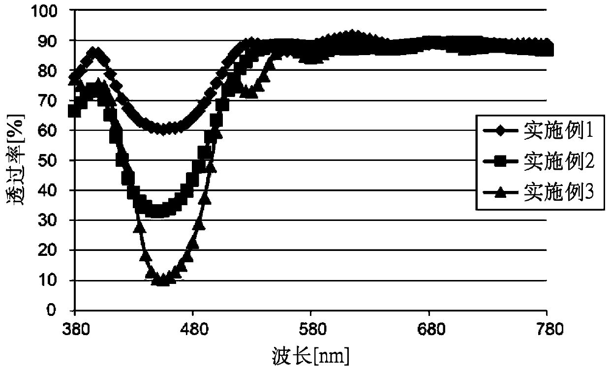
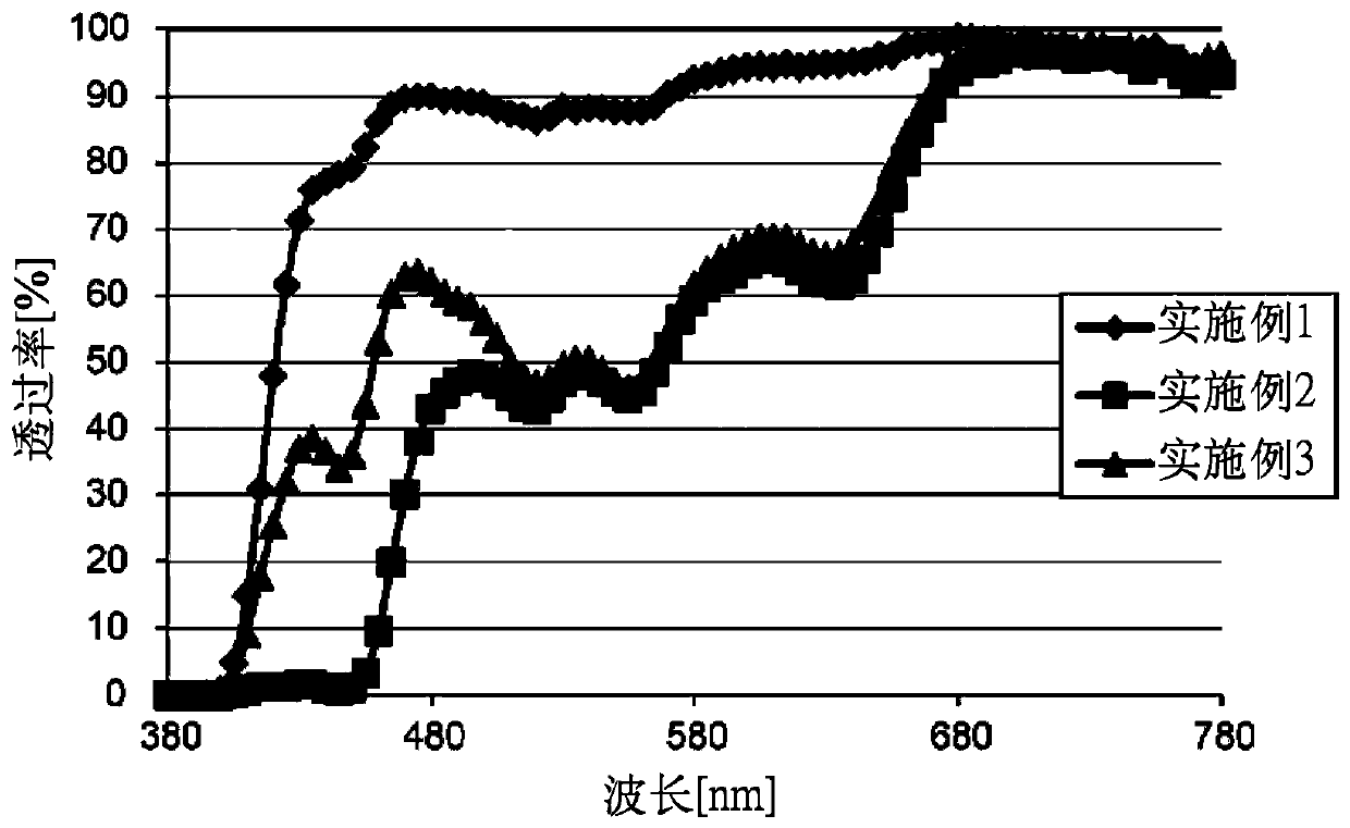
Embodiment 1
[0071]
[0072] Using the cholesteric liquid crystal coating liquid of preparation example 1, each light reflection layer was produced by the following procedure. As the plastic substrate, a PET film (A4100, thickness 50 μm, primer-free) manufactured by Toyobo Co., Ltd. was used.
[0073] (1) At room temperature, the coating solution of Preparation Example 1 was coated on a PET film using a wire bar so that the film thickness after drying would be 1.2 μm to form a coating film.
[0074] (2) The obtained coating film was heated at 150° C. for 5 minutes to remove the solvent to obtain a cholesteric liquid crystal phase. Next, UV was irradiated for 5 to 10 seconds with a high-pressure mercury lamp (manufactured by Harison Toshiba Lighting) with an output of 120 W to fix the cholesteric liquid crystal phase and form a light reflection layer on the PET film.
[0075] (3) The obtained light reflection layer was peeled from the PET film, and the optical film of this invention cont...
Embodiment 2
[0077]
[0078] Using the cholesteric liquid crystal coating liquids of formulation example 1 and formulation example 3, each light reflection layer was produced by the following procedure. A PET film (A4100, thickness 50 μm, primer-free) manufactured by Toyobo Co., Ltd. was used as the plastic substrate.
[0079] (1) At room temperature, the coating solution of Preparation Example 3 was coated on a PET film using a wire bar so that the film thickness after drying would be 1.2 μm to form a coating film.
[0080] (2) The obtained coating film was heated at 150° C. for 5 minutes to remove the solvent to obtain a cholesteric liquid crystal phase. Next, UV was irradiated for 5 to 10 seconds with a high-pressure mercury lamp (manufactured by Harison Toshiba Lighting) with an output of 120 W to fix the cholesteric liquid crystal phase and form a light reflection layer on the PET film.
[0081] (3) Through this operation, the light reflection layer L1 which reflects left circularl...
Embodiment 3
[0086]
[0087] Using the cholesteric liquid crystal coating liquids of formulation example 2 and formulation example 4, each light reflection layer was produced by the following procedure. A PET film (A4100, thickness 50 μm, primer-free) manufactured by Toyobo Co., Ltd. was used as a plastic substrate.
[0088] (1) At room temperature, the coating solution of Preparation Example 2 was coated on a PET film using a wire bar so that the film thickness after drying would be 1.8 μm to form a coating film.
[0089] (2) The obtained coating film was heated at 150° C. for 5 minutes to remove the solvent to obtain a cholesteric liquid crystal phase. Next, UV was irradiated for 5 to 10 seconds with a high-pressure mercury lamp (manufactured by Harison Toshiba Lighting) with an output of 120 W to fix the cholesteric liquid crystal phase and form a light reflection layer on the PET film.
[0090] (3) Through this operation, the light reflection layer R2 which reflects the right circul...
PUM
| Property | Measurement | Unit |
|---|---|---|
| thickness | aaaaa | aaaaa |
| glass transition temperature | aaaaa | aaaaa |
| thickness | aaaaa | aaaaa |
Abstract
Description
Claims
Application Information
 - R&D
- Intellectual Property
- Life Sciences
- Materials
- Tech Scout
- Unparalleled Data Quality
- Higher Quality Content
- 60% Fewer Hallucinations
Browse by: Latest US Patents, China's latest patents, Technical Efficacy Thesaurus, Application Domain, Technology Topic, Popular Technical Reports.
© 2025 PatSnap. All rights reserved.Legal|Privacy policy|Modern Slavery Act Transparency Statement|Sitemap|About US| Contact US: help@patsnap.com


