Novel medical bloodletting cup

A bloodletting tank, a new type of technology, applied in the field of new medical bloodletting tanks, can solve problems such as inconvenient operation, square mouth jamming, and limited rotation freedom, achieving low cost and avoiding cross-infection

Pending Publication Date: 2019-11-29
CENT HOSPITAL XUHUI DISTRICT SHANGHAI CITY
View PDF2 Cites 1 Cited by
  • Summary
  • Abstract
  • Description
  • Claims
  • Application Information

AI Technical Summary

Problems solved by technology

However, the cupping device described in this patent document adopts the cooperation of the end cap structure with a square opening and the orthogonal rib plate, which seriously limits the degree...

Method used


Image

  • Novel medical bloodletting cup
  • Novel medical bloodletting cup
  • Novel medical bloodletting cup

Examples


Embodiment 1

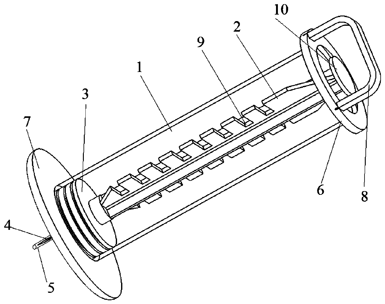
[0034] Please see attached figure 1 , with figure 1 It is a three-dimensional schematic diagram of a novel medical bloodletting tank of the present invention. A new type of medical bloodletting tank, comprising a cupping cylinder 1, a piston rod 2, a rubber plug 3, a bloodletting needle 4, and a needle sleeve 5; the cupping cylinder 1 is a hollow cylinder with two ends open, made of transparent medical plastic material , the upper end of the tank mouth is provided with a pressure flange 6, and the lower end of the tank mouth is provided with a protective flange 7; the upper part of the cupping cylinder 1 is provided with a card seat 8, and the card seat 8 spans the cupping The upper end of the cylinder 1 is directly above the opening of the cupping cylinder 1, and the horizontal direction is far away from the center of the upper end of the cupping cylinder 1; the piston rod 2 is a cross rod structure composed of wide structural ribs and narrow structural ribs orthogonally for...

Embodiment 2

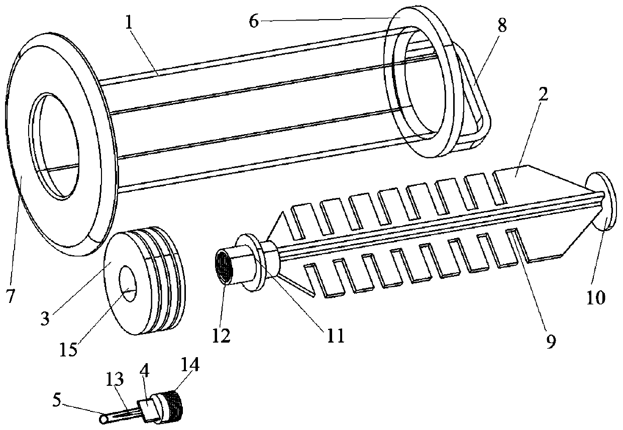
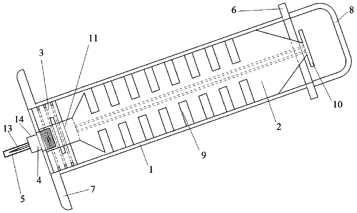
[0038] Please see attached Image 6 , with Image 6 It is a three-dimensional schematic diagram of another new type of medical bloodletting tank of the present invention. A new type of medical bloodletting tank, comprising a cupping cylinder 1, a piston rod 2, a rubber plug 3, a bloodletting needle 4, and a needle sleeve 5; the cupping cylinder 1 is a hollow cylinder with two ends open, made of transparent medical plastic material , the upper end of the tank mouth is provided with a pressure flange 6, and the edge of the lower end of the tank mouth is smooth and rounded; The upper end of the cylinder 1 is directly above the opening of the cupping cylinder 1, and the horizontal direction is far away from the center of the upper end of the cupping cylinder 1; the piston rod 2 is a cross rod structure composed of wide structural ribs and narrow structural ribs orthogonally formed, and the two sides of the wide structural ribs are provided with A plurality of draw-in slots 9, th...


PUM


Abstract

The invention belongs to the technical field of medical equipment, and relates to a novel medical bloodletting cup. The bloodletting cup includes a cupping cylinder, a piston rod, a rubber plug, a bloodletting needle and a needle cannula; the cupping cylinder is a hollow cylinder with two open ends; a clamping seat is arranged above an opening located in the upper end of the cupping cylinder; thepiston rod is provided with a plurality of clamping grooves; the upper end of the piston rod is provided with a grip, and the lower end is provided with a connector; the rubber plug is provided with aconnection groove; the bloodletting needle is detachably connected with the piston rod; the piston rod is connected with the rubber plug; the piston rod is movably connected with the cupping cylinder; and the needle cannula has a cylindrical hollow structure with one open end, and sleeves a body of the bloodletting needle. The bloodletting cup provided by the invention has the following beneficial effects: the operation is simple, safe and reliable, bloodletting and cupping are combined, a position can be chose to apply the needle, the manner of applying the needle is not hindered, and the bloodletting cup is simple and reliable, and has low costs and the detachable needle body.

Description

technical field [0001] The invention relates to the technical field of medical instruments, in particular to a novel medical bloodletting tank. Background technique [0002] Bloodletting and cupping therapy is widely used in the clinical field of medicine. It is a common treatment method of traditional Chinese medicine. The traditional blood cupping process requires a plum blossom needle to puncture the skin, and then cover the skin with cupping. During the operation, various instruments are used together, and the operation steps are cumbersome . In addition, at present, most of the clinically used cupping cups are sterilized and used repeatedly, and the cost is relatively high. The production cost of this bloodletting cup is low, and it is one-time use, which can prevent cross-infection to the greatest extent. The negative pressure suction required is also different, and the negative pressure suction of traditional cupping cans is difficult to control and requires a lot of...

Claims


Application Information

Patent Timeline
IPC IPC(8): A61B17/00A61H9/00A61M1/08
CPCA61B17/00A61H9/0057A61H2201/10A61M1/08A61M2205/05
Inventor 胡艳美李建萍杨建梅牛燕霞王晓宇王鑫王茜
Owner CENT HOSPITAL XUHUI DISTRICT SHANGHAI CITY
Why Eureka
Try Eureka