Diffusion type porous medium gas fuel combustor

A technology of porous media and gas fuel, applied to gas fuel burners, burners, combustion methods, etc., can solve the problems of small lean burn limit combustion rate and stability, load adjustment range, difficulty in manufacturing, tempering, etc., to achieve Avoid tempering phenomenon, save energy, and achieve uniform density distribution

Inactive Publication Date: 2010-06-16
NORTHEASTERN UNIV
View PDF0 Cites 14 Cited by
  • Summary
  • Abstract
  • Description
  • Claims
  • Application Information

AI Technical Summary

Problems solved by technology

[0004] Premixed combustion in porous media has many advantages: smaller lean-burn limit, higher combustion rate and stability, wide load adjustment range, high combustion intensity, small burner volume, complete combustion, etc. Pollutants in combustion products For example, the content of NOx, CO, etc. is very small; but at the same time, we found that the porous media burner using complete premixed combustion still has the following defects: because there is a premixed air and gas mixture under the small porous media in the premixed area. When the combustion intensity is small, tempering may occur; because the burner has high requirements on the material of the small pore medium, such as high temperature resistance, and the thermal shock resistance of ceramic foam with a small pore size (50-60PPI) is not good. good and hard to make

Method used


Image

  • Diffusion type porous medium gas fuel combustor
  • Diffusion type porous medium gas fuel combustor
  • Diffusion type porous medium gas fuel combustor

Examples


Embodiment 1

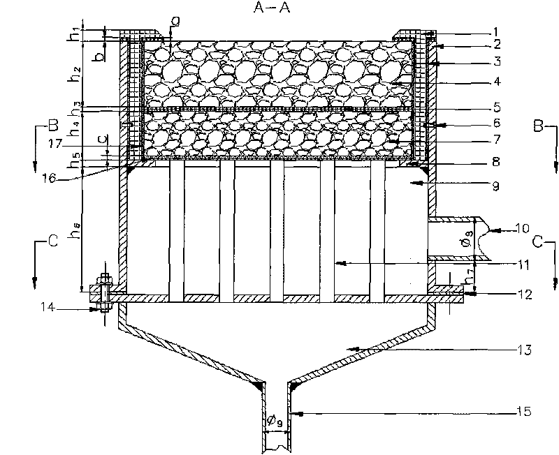
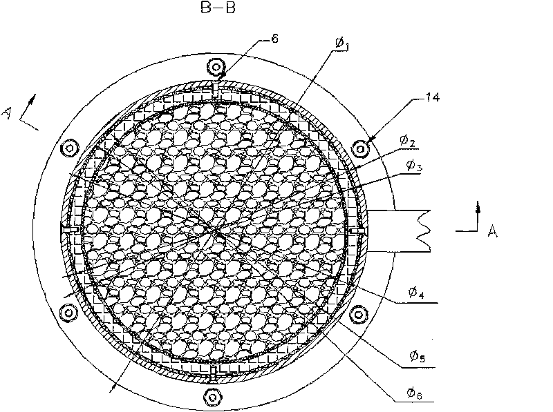
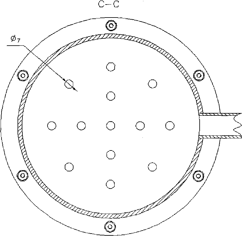
[0044] Diffusion porous media gas fuel burner structure such as figure 1 As shown, the A-A section view is as follows figure 2 As shown, the B-B section view structure is as follows image 3 As shown, the burner is mainly composed of a refractory casing 1, a casing 2, a tray 8, a gas distribution pipe 11 and a gas distribution tank 13, and the structure of the tray 8 is as follows Figure 4 As shown, the tray hole in the tray 8 connects the upper and lower end faces of the tray, the bottom end of the casing 2 is connected with the top plate of the gas distribution tank 13, and the interior of the casing 2 is sequentially provided with a refractory sleeve 1, a tray 8 and a gas Distributor pipe 11, the bottom end of refractory casing 1 is in contact with tray 8, and the outer edge of tray 8 is welded and fixed with shell 2; Internal communication; the refractory casing 1 is provided with large-pore porous media 4, small-pore porous media 7 and lower metal fibers 16 from top t...

Embodiment 2

[0068] The structure of the diffused porous medium gas fuel burner is the same as that in Embodiment 1; the material of the large-pore porous medium is calcium oxide-based zirconia, and the material of the small-pore porous medium is yttrium oxide-based zirconia.

[0069] Geometric dimensions are with embodiment 1.

[0070] Using 3# burner (φ 4 =170mm), the combustion intensity is 900~2000kw / m respectively under the condition of no air preheating 2 The combustion test, the test data are shown in Table 4.

[0071] Table 4

[0072]

[0073]

[0074] Using 3# burner (φ 4 =170mm), the combustion intensity is 900~2000kw / m respectively under the condition of air preheating to 300℃ 2 The combustion test, the test data are shown in Table 5.

[0075] table 5

[0076]

[0077]

Embodiment 3

[0079] Diffusion porous media gas fuel burner structure such as Figure 5 As shown, the A-A section view is as follows Figure 6 As shown, the B-B section view structure is as follows Figure 7 As shown, the structure of the diffused porous media gas fuel burner is as follows figure 1 As shown, the A-A section view is as follows figure 2 As shown, the B-B section view structure is as follows image 3 As shown, the burner is mainly composed of a refractory casing 1, a casing 2, a tray 8, a gas distribution pipe 11 and a gas distribution tank 13, and the structure of the tray 8 is as follows Figure 8 As shown, the tray hole in the tray 8 connects the upper and lower end faces of the tray, the bottom end of the casing 2 is connected with the top plate of the gas distribution tank 13, and the interior of the casing 2 is sequentially provided with a refractory sleeve 1, a tray 8 and a gas The distribution pipe 11 and the bottom end of the refractory sleeve 1 are in contact wi...


PUM


Abstract

A diffusion type porous medium gas fuel combustor comprises a shell, an air duct and a fire-resistant casing pipe, the air duct is connected with the shell, the bottom end of the shell is connected with the top plate of a gas flow dividing tank, the shell is internally provided with the fire-resistant casing pipe, a tray and a gas flow dividing tube from top to bottom, the bottom end of the fire-resistant casing pipe is contacted with the tray, the tray is fixed on the shell or the gas flow dividing tube, the bottom end of the gas flow dividing tube is fixed on the top plate of the gas flow dividing tank, and the gas flow dividing tube and the gas flow dividing tank are communicated internally; the fire-resistant casing pipe is provided with macro porous medium, micro porous medium and lower layer metal fiber from top to bottom, and the lower layer metal fiber is connected with the tray and the gas flow dividing tube simultaneously. The inventive diffusion type porous medium gas fuel combustor can be used for efficiently avoiding tempering when combustion intensity is stronger, thus achieving the effects of protecting micro porous medium and saving energy.

Description

technical field [0001] The invention relates to a gas fuel burner, in particular to a diffusion type porous medium gas fuel burner. Background technique [0002] In the combustion of high calorific value gas fuels, in terms of material properties, porous media has the characteristics of high temperature resistance, oxidation resistance, and corrosion resistance. Stainless steel, alloys, and ceramics have all been used as research objects by scholars at home and abroad. In terms of structure, when the aperture is relatively large, the radiation penetrates farther and the temperature rises faster; when the aperture is relatively small, the relative optical thickness of the porous medium is relatively large, which can shield radiation and have a good thermal storage effect. At present, the technology of adding porous media in the burner is gradually being paid attention to. [0003] Li Wenwen and others proposed "a porous metal medium burner for burning low calorific value gas...

Claims


Application Information

Patent Timeline
Patent Type & Authority Applications(China)
IPC IPC(8): F23D14/12F23D14/02
Inventor 李本文田溪岩胡章茂赵磊
Owner NORTHEASTERN UNIV
Why Eureka
Try Eureka