Adjustable Grip Applicator

A technology of applying device and clamping distance, which is applied in the field of medical equipment, can solve the problems of large size differences, etc., and achieve the effect of strong adaptability and convenient use

Active Publication Date: 2021-03-12
浙江朗特医疗科技有限公司
View PDF8 Cites 0 Cited by
  • Summary
  • Abstract
  • Description
  • Claims
  • Application Information

AI Technical Summary

Problems solved by technology

The current method for ligation to stop bleeding is to use clips such as ligation clips and tissue clips to stop bleeding, but there is a problem in using clips such as ligation clips and tissue clips (the structure of the ligation clips and tissue clips is basically the same) to stop bleeding, because these clips are in practical use. During the process, the clip must be in

Method used


Image

  • Adjustable Grip Applicator
  • Adjustable Grip Applicator
  • Adjustable Grip Applicator

Examples


Embodiment 1

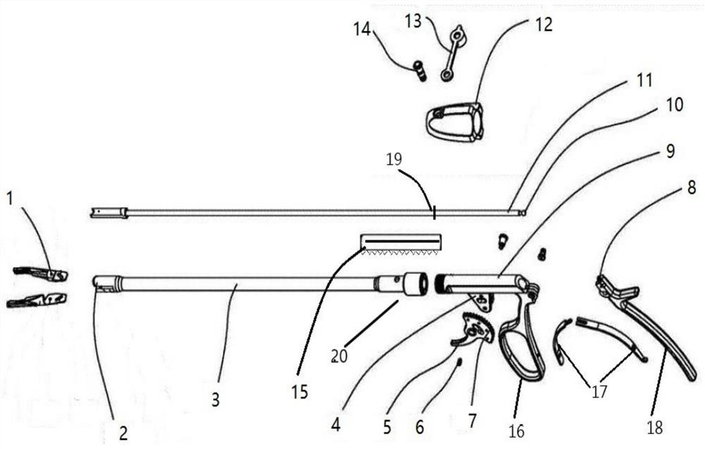
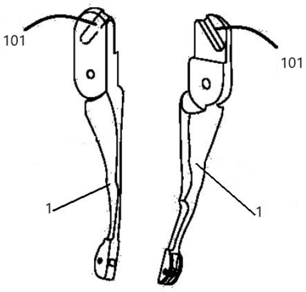
[0026] as attached figure 1 and attached figure 2 As shown, a kind of adjustable clip distance applying device comprises fixed handle 16, movable handle 18, elastic member 17, operating sleeve 3, operating rod 11 and adjustment structure, and one end of fixed handle 16 is fixed on the operating sleeve 3, and the movable One end of the handle 18 is rotated and matched with the fixed handle 16. The elastic member 17 is arranged between the movable handle 18 and the fixed handle 16. The elastic member 17 is used to bounce the movable handle 18 and the fixed handle 16. Inside the operating sleeve 3, the operating rod 11 is provided with a mounting part, which is used to install the chuck 1, and the mounting part is located outside the operating sleeve 3. The adjustment structure includes a slider 15 and a trigger 5, and the slider 15 and the trigger 5 Both are provided with a gear surface 7, the slider 15 and the trigger 5 are meshed together through the gear surface 7, the slid...

Embodiment 2

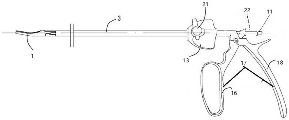
[0034] as attached figure 2 , attached image 3 and attached Figure 4 As shown, an adjustable clip distance applying device includes a fixed handle 16, a movable handle 18, an elastic member 17, an operating sleeve 3, and an operating rod 11. One end of the fixed handle 16 is fixed on the operating sleeve 3, and one end of the movable handle 18 is Together with the fixed handle 16, the elastic member 17 is arranged between the movable handle 18 and the fixed handle 16, the elastic member 17 is used to bounce the movable handle 18 and the fixed handle 16, and the operating rod 11 is movably sleeved on the operation sleeve 3, the operating rod 11 is provided with a mounting part, which is used to install the chuck 1, and the mounting part is located outside the operating sleeve 3. The adjustment structure includes an adjusting sleeve 22 and a thread 1101, and one end of the operating rod 11 is provided with a thread 1101. The adjusting sleeve 22 is installed on the thread 11...


PUM


Abstract

The invention discloses a clip-distance-adjustable applicator. The clip-distance-adjustable applicator comprises a fixed handle, a movable handle, an elastic piece, an operating sleeve, an operating rod and an adjusting structure, wherein one end of the fixed handle is fixed on the operating sleeve; one end of the movable handle is in running fit with the fixed handle; the elastic piece is arranged between the movable handle and the fixed handle; the elastic piece is used for separating the movable handle from the fixed handle in a flicking manner; the operating rod is movably arranged in theoperating sleeve in a sleeving manner; a mounting portion is arranged on the operating rod; the mounting portion is used for mounting a chuck and is positioned outside the operating sleeve; the adjusting structure is arranged on the operating sleeve or the operating rod or between the operating rod and the operating sleeve; the adjusting device is used for adjusting the distance between the mounting portion and the operating sleeve; and the movable handle is used for driving the operating rod to move in the operating sleeve.

Description

technical field [0001] The invention relates to the field of medical instruments, in particular to an adjustable clip distance applying device. Background technique [0002] In order to fully expose the surgical field during the surgical operation, it is necessary to ligate the broken blood vessels in the incision to prevent bleeding. The current method for ligation to stop bleeding is to use clips such as ligation clips and tissue clips to stop bleeding, but there is a problem in using clips such as ligation clips and tissue clips (the structure of the ligation clips and tissue clips is basically the same) to stop bleeding, because these clips are in practical use. During the process, the clip must be installed on the clip applier before it can be used (the two clips of the clip are installed on the clip applier respectively during the specific installation), but because the size of the clips of different specifications varies greatly, and each size The clip can only be us...

Claims


Application Information

Patent Timeline
IPC IPC(8): A61B17/128A61B17/12A61B17/122
CPCA61B17/12A61B17/122A61B17/1285A61B2017/12004
Inventor 吴康平王锐李政沈盛杰
Owner 浙江朗特医疗科技有限公司
Why Eureka
Try Eureka