
A fully automatic round head barrel hook forming machine

A hook forming machine, fully automatic technology, applied in the field of automatic round head barrel hook forming machine, can solve the unfavorable application of steel wire handle forming machine, the difficulty of guaranteeing the degree of bending consistency, the bending degree of steel wire tends to be consistent, etc. Achieve the effect of meeting the requirements of automatic installation production line, improving automation level and production efficiency, and meeting production requirements

Active Publication Date: 2017-06-16
CHANGZHOU PUHE PLASTIC
View PDF1 Cites 0 Cited by
  • Summary
  • Abstract
  • Description
  • Claims
  • Application Information

AI Technical Summary

Problems solved by technology

This method of operation has the following disadvantages: First, the degree of consistency of bending is difficult to guarantee, that is, the quality of the product is difficult to guarantee. Bending is closely related to the operator's experience; second, the operator's labor intensity is high and the efficiency is low
By replacing the forming device, the fully automatic intelligent steel wire handle forming machine of this application can also produce round head barrel hooks, but the steel wire feeding device and unloading device in this application are not conducive to the use of the steel wire handle forming machine in a production line The application of the barrel hook cannot meet the requirements of automatic installation after the barrel hook is formed, so it is urgent to improve it to meet the production demand

Method used


Image

  • A fully automatic round head barrel hook forming machine
  • A fully automatic round head barrel hook forming machine
  • A fully automatic round head barrel hook forming machine

Examples


Embodiment

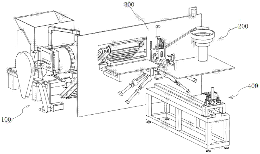
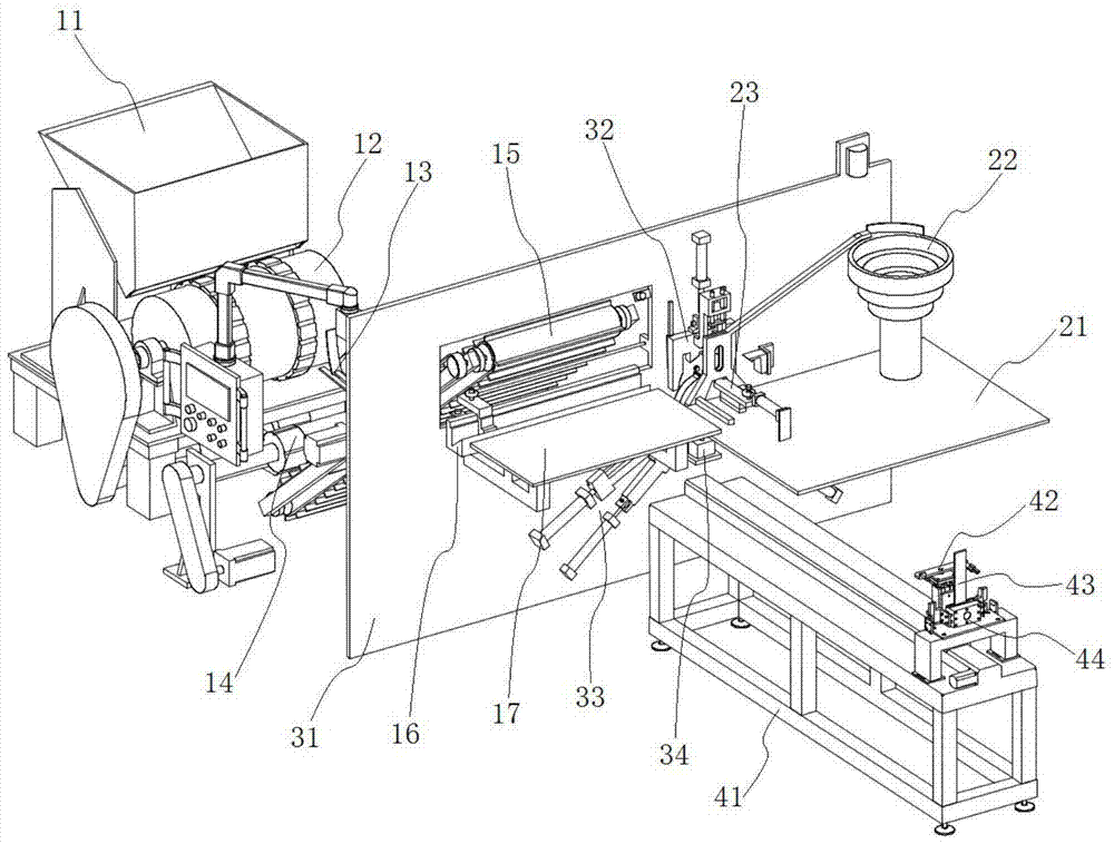
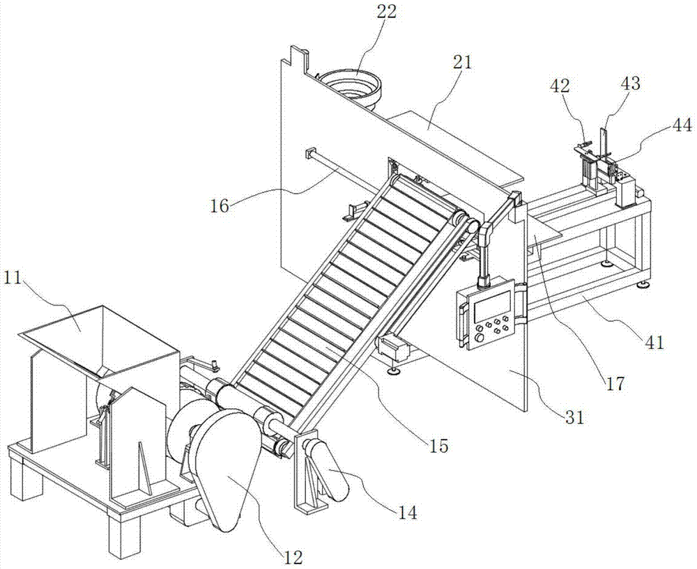
[0052] to combine figure 1 , figure 2 and image 3 As shown, a fully automatic round head bucket hook forming machine in this embodiment includes a steel wire feeding device 100, a handle tube feeding device 200, a forming device 300, a retrieving and shaping device 400 and a control system, wherein,

[0053] The handle tube feeding device 200 is arranged in front of the forming device 300, and is used to push the handle tube onto the forming device 300, which includes a workbench 21, a handle tube material selection and storage mechanism 22 and a handle tube feeding mechanism 23, The handle tube material selection and storage mechanism 22 and the handle tube feeding mechanism 23 are installed on the workbench 21, and the handle tube feeding mechanism 23 is used to push the handle tube in the handle tube material selection and storage mechanism 22 to the forming device 300;

[0054] Steel wire feeding device 100 is located at the rear of forming device 300, and it comprise...


PUM


Abstract

The invention discloses a fully-automatic round-head barrel hook forming machine belonging to the field of wire bending machines. The fully-automatic round-head barrel hook forming machine comprises a steel wire feeding device, a handle tube feeding device, a forming device, a fetching and shaping device and a control system, wherein the handle tube feeding device is arranged in front of the forming device; the steel wire feeding device is arranged at the rear of the forming device; the fetching and shaping device is arranged in front of the forming device, is located below the handle tube feeding device and is composed of a grabbing mechanism, a locating mechanism and a shaping mechanism; and all the steel wire feeding device, the handle tube feeding device, the forming device and the fetching and shaping device are automatically controlled by the control system to sequentially finish the actions of handle tube feeding, steel wire feeding, barrel hook forming as well as fetching and shaping. By using the fully-automatic round-head barrel hook forming machine, a barrel hook not only can be fully-automatically produced, but also can be corrected and shaped after being formed to make preparation for the next installation of the barrel hook, so that the requirement of an automatic installation production line of the barrel hook is met, and the automatic level and production efficiency of vessels such as barrels and tanks are greatly increased.

Description

technical field [0001] The invention relates to a barrel hook forming machine, more specifically, relates to a fully automatic round head barrel hook forming machine which can be used in a production line. Background technique [0002] The structure of the barrel hook (also called steel wire handle or steel wire handle) used for barrel containers seems simple, but in order to meet the strength and corresponding mechanical requirements, the shape of the barrel hook is relatively special, which is specifically manifested as the inflection point and / or There are many arc transition points, and the requirements for the forming process are relatively strict. In addition, since the barrel hook is a non-standard product, it is not possible to obtain special forming equipment from commercial channels. [0003] At present, most of the above-mentioned barrel hooks are formed by workers punching and bending with self-made molds. Specifically, the corresponding modules are fixed on the...

Claims


Application Information

Patent Timeline
Patent Type & Authority Patents(China)
IPC IPC(8): B21F45/00B21F1/00B21F23/00
CPCB21F1/00B21F23/00B21F45/00
Inventor 杜逸帆杜建平
Owner CHANGZHOU PUHE PLASTIC
Learn More