Main transformer cooling device

A technology of cooling device and main transformer, applied in transformer/inductor casing, transformer/inductor cooling, transformer/inductor components, etc., can solve problems such as poor cooling effect, single cooling method, transformer damage, etc., to achieve Prevent damage to the main body of the transformer, quickly cool down and dissipate heat, and facilitate operation

Inactive Publication Date: 2019-11-29
STATE GRID SHANDONG ELECTRIC POWER CO LAIZHOU POWER SUPPLY CO
View PDF11 Cites 10 Cited by
  • Summary
  • Abstract
  • Description
  • Claims
  • Application Information

AI Technical Summary

Problems solved by technology

[0004] The purpose of the present invention is to solve the problem in the prior art that the cooling and cooling structure of dry-type transformers mostly adopts air cooling, the cooling method is single, the cooling effect is not good, and the transformer is easily damaged due to excessive temperature in hot summer, so Can not meet the shortcomings of people's needs, and proposed a main transformer cooling device

Method used


Image

  • Main transformer cooling device
  • Main transformer cooling device
  • Main transformer cooling device

Examples


Embodiment 1

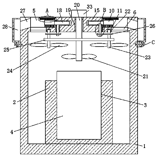
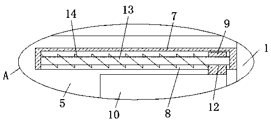
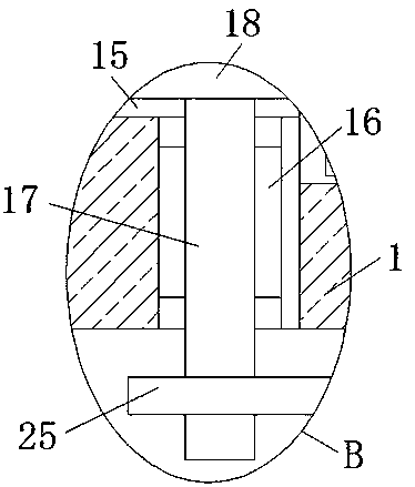
[0028] refer to Figure 1-5 , a cooling device for a main transformer, comprising a housing 1 set in a hollow structure, a mounting seat 2 is fixedly installed on the inner wall of the bottom of the housing 1, a placement groove 3 is opened on the top of the mounting seat 2, and a transformer is placed in the placement groove 3 The main body 4 and the top of the housing 1 are provided with two vents 5, the same dust-proof filter plate 6 is fixedly installed on the inner wall of both sides of the vent 5, and the inner wall of the side where the two vents 5 are close to each other is fixedly installed There are fixed plates 7, and the bottoms of the two fixed plates 7 are provided with chute 8, and sliders 9 are slidably installed in the two chute 8, and the bottom ends of the two sliders 9 respectively extend to the corresponding fixed plates 7 The bottom of the two brush plates 10 is fixedly installed with a brush plate 10, and the bottom ends of the two brush plates 10 are fi...

Embodiment 2

[0039] refer to Figure 1-5 , a cooling device for a main transformer, comprising a shell 1 set as a hollow structure, the bottom inner wall of the shell 1 is fixedly connected with a mounting base 2 by bolts, the top of the mounting base 2 is provided with a placement groove 3, and the placement groove 3 is placed There is a transformer main body 4, two vents 5 are opened on the top of the housing 1, the same dust-proof filter plate 6 is fixedly connected to the inner walls on both sides of the vents 5 by bolts, and the inner wall of the side where the two vents 5 are close to each other Both of them are fixedly connected with fixed plates 7 by bolts, and the bottoms of the two fixed plates 7 are provided with chute 8, and slide blocks 9 are slidably installed in the two chute 8, and the bottom ends of the two slide blocks 9 respectively extend to The bottom of the corresponding fixing plate 7 is fixedly connected with a brush plate 10 by bolts, and the bottom ends of the two...


PUM


Abstract

The invention belongs to the field of cooling devices, and particularly relates to a main transformer cooling device. Air cooling is mostly adopted for the cooling structure of an existing dry-type transformer, there is only a single cooling mode, the cooling effect is poor, the transformer is easily damaged due to over-high temperature in hot summer, and thus, the requirements of people cannot bemet. In order to solve the problem, the scheme as follows is put forward: the main transformer cooling device comprises a shell of a hollow structure, a mounting base is fixedly mounted on the bottominner wall of the shell, a placing groove is formed in the top of the mounting base, a transformer body is placed in the placing groove, two ventilation openings are formed in the top of the shell, and a same dustproof filter plate is fixedly mounted on the inner walls of the two sides of each ventilation opening. The main transformer cooling device is simple in structure and convenient to operate. Dust adhered to the dustproof filter plates can be cleaned and collected while the transformer body can be rapidly cooled, the situation that the transformer body is damaged due to too high temperature is prevented, and therefore, the requirements of people are met.

Description

technical field [0001] The invention relates to the technical field of cooling devices, in particular to a cooling device for a main transformer. Background technique [0002] According to relevant data records, dry-type transformers have developed rapidly in the past 20 years, especially in distribution transformers, dry-type transformers account for an increasing proportion. 30%-40%, the safe operation and service life of dry-type transformers depend largely on the safety and reliability of transformer winding insulation. In addition to the increase of its own temperature, it will also increase the temperature of the surrounding medium. When the temperature of the winding exceeds the heat resistance limit of the insulating material, the insulating material will be damaged. This is one of the main reasons why the transformer cannot work normally, and it will reduce The service life of the transformer, therefore, the cooling of the dry-type transformer becomes the focus of ...

Claims


Application Information

Patent Timeline
Patent Type & Authority Applications(China)
IPC IPC(8): H01F27/02H01F27/08
CPCH01F27/02H01F27/025H01F27/085
Inventor 赵静刘勇李林宇张宝鹏袁希萍丁忠民李东胡志波韩同庆孙伟任松林盛英俊刘亚东王伟新秦雪梅杨秋云张卫荣王国亮暴敏王浩
Owner STATE GRID SHANDONG ELECTRIC POWER CO LAIZHOU POWER SUPPLY CO
Why Eureka
Try Eureka