Floating slab track structure based on external hydraulic type inerters and internal hydraulic type inerters

A technology of inerters and floating plates, which is applied in the field of rail applications, can solve the problems of poor low-frequency vibration reduction, high requirements for liquid damping material composition, and low utilization rate of damping energy consumption, and achieve the goal of expanding the range and improving the vibration isolation effect Effect

Pending Publication Date: 2019-12-03
SHENZHEN UNIV
View PDF10 Cites 5 Cited by
  • Summary
  • Abstract
  • Description
  • Claims
  • Application Information

AI Technical Summary

Problems solved by technology

[0006] The purpose of the present invention is to provide a floating slab track structure based on external and built-in hydraulic inerters, aiming to solve the poor low-frequency vibration reduction effect and high composition of liquid damping materials in the existing floating slab track technology And the problem of low utilization rate of damping energy consumption

Method used


Image

  • Floating slab track structure based on external hydraulic type inerters and internal hydraulic type inerters
  • Floating slab track structure based on external hydraulic type inerters and internal hydraulic type inerters
  • Floating slab track structure based on external hydraulic type inerters and internal hydraulic type inerters

Examples


Embodiment 1

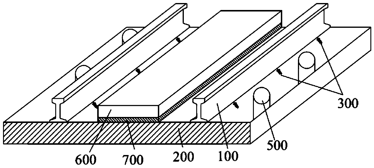
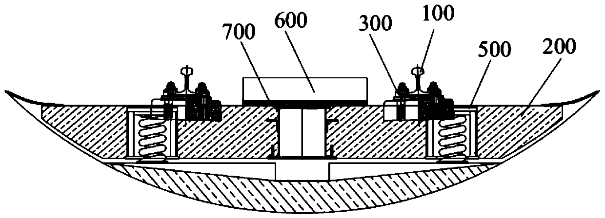
[0033] See Figure 1 to Figure 5 ;Such as figure 1 and figure 2 As shown, this embodiment provides a floating slab track structure based on an external hydraulic inerter, including: a steel rail 100, a track plate 200, a fastener 300, a horizontal limit device (not shown), and a shear hinge (not shown), vibration isolator 500, weight-increasing boss 600 and elastic element 700; wherein, the track plate 200 is arranged below the rail 100, and the track plate 200 and the rail 100 pass through the The fastener 300 is fixedly connected; the horizontal limiting device is arranged on both sides of the track plate 200, and can be used to limit the horizontal position of the track plate 200; the shear hinge is used to place the track The plate 200 is connected to another track plate 200, so that multiple track plates 200 are connected as a whole; the vibration isolator 500 is arranged inside the track plate 200, and is located on the outside or inside of the lower surface of the ra...

Embodiment 2

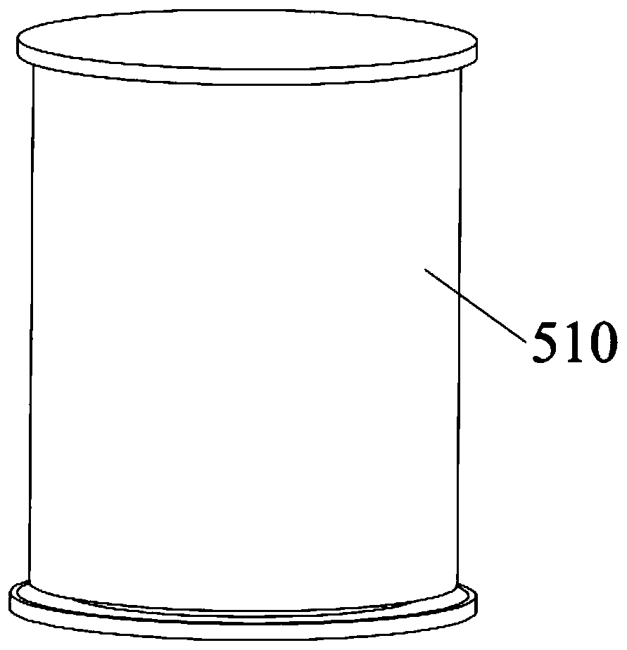
[0052] See figure 1 , figure 2 , image 3 as well as Figure 7 , this embodiment provides a floating plate track structure based on a built-in hydraulic inertial container; the difference from the first embodiment above is that in this embodiment, a built-in hydraulic inertial container (not marked); wherein, the built-in hydraulic inerter includes an elongated spiral tube 530 , a liquid damper (not shown) and a helical steel spring 540 .

[0053] The elongated spiral tube 530 is arranged inside the inner cylinder 520, and the elongated spiral tube 530 is coiled on the inner wall of the inner cylinder 520, and is fixedly connected with the inner cylinder 520; the liquid damping seal is inside the inner cylinder 520 The inside of the inner tube 520; the coiled steel spring 540 is arranged inside the inner tube 520, and the coiled steel spring 540 is embedded in the inner tube 520, and the bottom of the coiled steel spring 540 is in contact with the inner tube 520. The bott...


PUM


Abstract

The invention discloses a floating slab track structure based on external hydraulic type inerters and internal hydraulic type inerters. The floating slab track structure based on the external hydraulic type inerters and the internal hydraulic type inerters comprises steel rails, a track slab, fasteners, a horizontal limiting device, a shear hinge, and vibration isolators arranged at the outer sides of the lower parts of the steel rails, wherein the steel rails are fixedly connected to the track slab through the fasteners; the track slab is fixedly connected to another track slab through the shear hinge; the vibration isolators are fixedly connected to the track slab; the external hydraulic type inerters and the internal hydraulic type inerters are arranged in the vibration isolators; eachexternal hydraulic type inerter is inlaid between an inner cylinder and an outer cylinder of each vibration isolator; and each internal hydraulic type inerter is inlaid inside the inner cylinder of each vibration isolator. By arranging the external hydraulic type inerters and the internal hydraulic type inerters, the floating slab track structure solves the problems of a poor low-frequency vibration reduction effect, high requirements on components of liquid damping materials, and low utilization ratio of damping dissipation energy in the existing floating slab technology.

Description

technical field [0001] The invention relates to the field of track application technology, more specifically, it relates to a floating plate track structure based on external and internal hydraulic inerters. Background technique [0002] Due to the advantages of large carrying capacity, low energy consumption, and convenience, urban rail transit in my country has developed rapidly in recent years. By the end of 2018, a total of 185 rail transit operating lines had been opened in 35 cities in my country, with a total length of 5761.4 However, the problems of environmental vibration and noise pollution brought by urban rail transit along the line have become increasingly prominent, seriously affecting people's daily life and work. The development of new technologies for reducing vibration and noise in rail transit has important scientific significance and socio-economic value. [0003] As a special vibration reduction method in the vibration and noise reduction technology of ur...

Claims


Application Information

Patent Timeline
IPC IPC(8): E01B1/00E01B19/00
CPCE01B1/002E01B19/00
Inventor 周锐杜彦良张颖周瑜
Owner SHENZHEN UNIV
Why Eureka
Try Eureka