Solid rocket engine, method for restraining residual propellant for propellant loading of solid rocket engine and combustion chamber structure

A technology of solid rockets and combustion chambers, which is applied to rocket engine devices, machines/engines, mechanical equipment, etc. It can solve problems such as longer working hours, reduced thrust, and impact on the overall performance of the engine, so as to improve strike accuracy and eliminate dragging The effect of the tail phenomenon

Inactive Publication Date: 2019-12-03
湖北三江航天江北机械工程有限公司
View PDF5 Cites 6 Cited by
  • Summary
  • Abstract
  • Description
  • Claims
  • Application Information

AI Technical Summary

Problems solved by technology

[0004] Usually, the simple round-hole-shaped grain has no residual charge, while the inner-side burning grain with complex inner holes (various shapes other than the round-hole shape) has a certain amount of residual charge in the late stage of solid rocket motor operation, and the residual charge burns Eventually, the thrust will be reduced and the working time will be longer. This phenomenon is called tailing phenomenon, which seriously affects the overall performance of the engine.

Method used


Image

  • Solid rocket engine, method for restraining residual propellant for propellant loading of solid rocket engine and combustion chamber structure
  • Solid rocket engine, method for restraining residual propellant for propellant loading of solid rocket engine and combustion chamber structure
  • Solid rocket engine, method for restraining residual propellant for propellant loading of solid rocket engine and combustion chamber structure

Examples


Embodiment Construction

[0025] The present invention will be further described in detail below in conjunction with the accompanying drawings and specific embodiments.

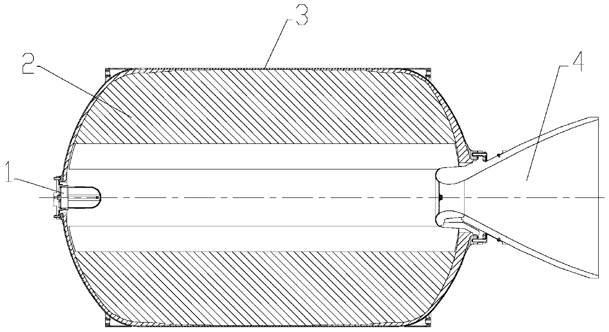
[0026] Such as figure 1 , figure 2 Shown is a solid rocket motor in the prior art, and its structure has been described in detail in the background technology section, and will not be repeated here.

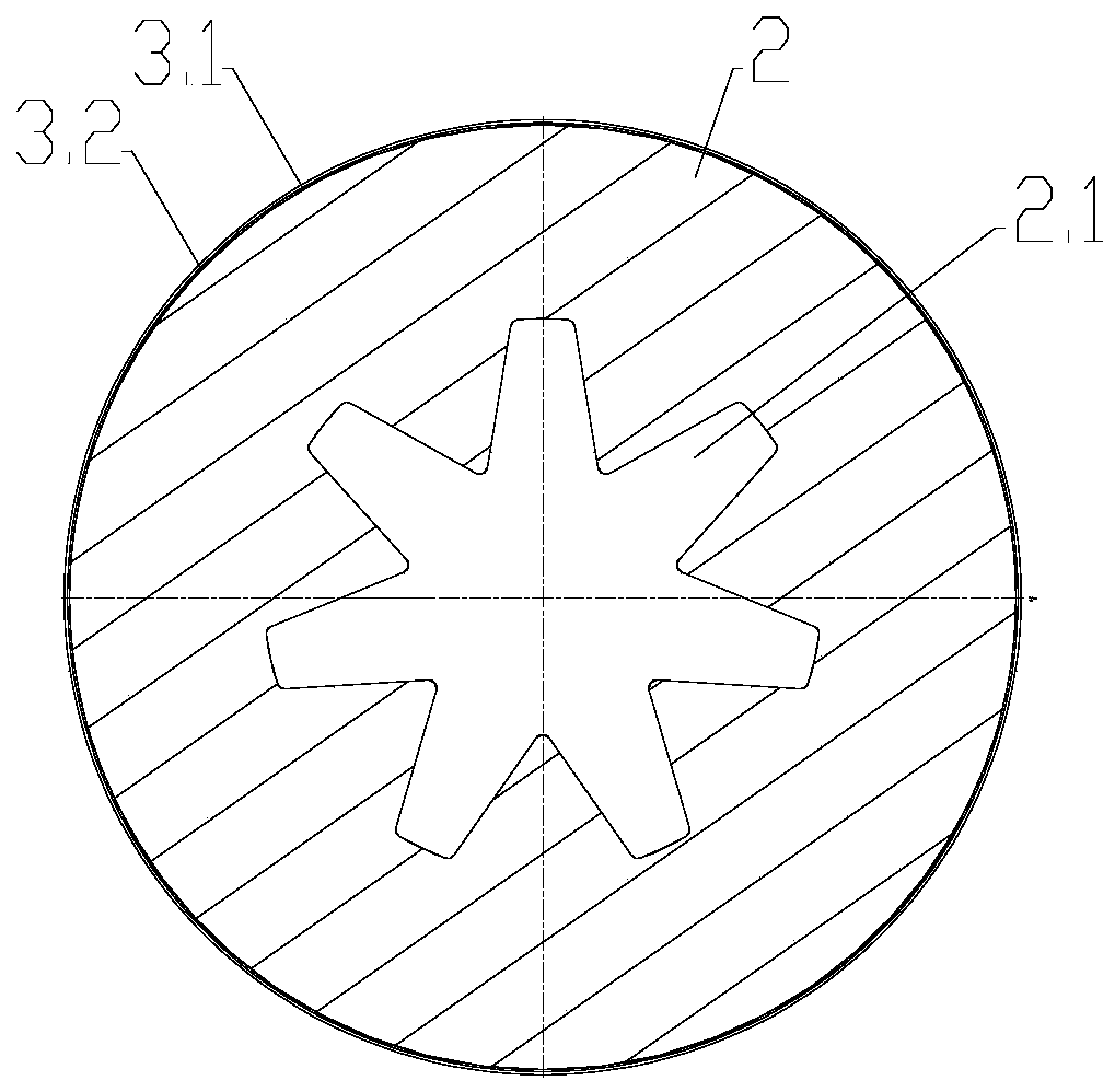
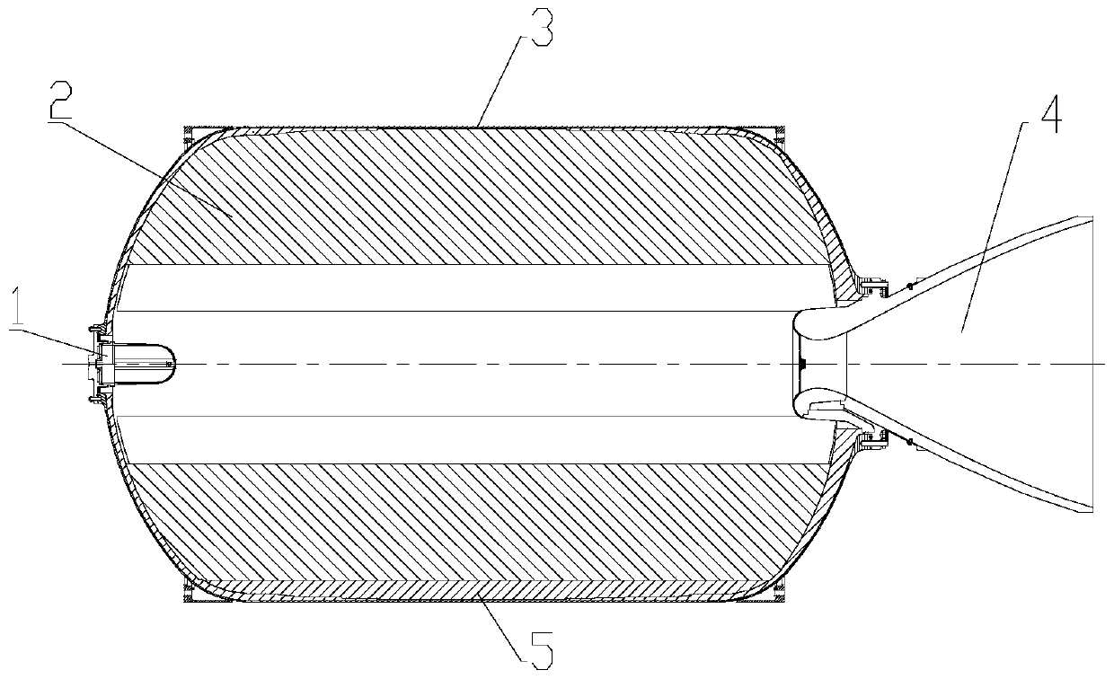
[0027] Such as Figure 3-5 As shown, the solid rocket motor ignition device 1 designed by the present invention, the grain 2, the combustion chamber 3 and the nozzle 4, the combustion chamber 3 includes the combustion chamber shell 3.1, the combustion chamber heat insulation layer 3.2, and the grain 2 has a star shape For the grain column in the inner hole, a residual medicine suppression member 5 is also arranged between the combustion chamber heat insulation layer 3.2 and the grain column 2 .

[0028] Remaining drug suppression part 5 is determined through the following steps:

[0029] 1) Determine the shape and position of the re...


PUM


Abstract

The invention discloses a method for inhibiting residual propellant for propellant loading of a solid rocket engine. The method comprises the following steps: 1) determining the shape and position ofthe residual propellant causing trailing of the solid rocket engine in the later working period; 2) arranging a residual propellant inhibiting piece which is completely the same as the residual propellant in shape and is made of a material which cannot provide thrust at the original position; and 3) filling the combustion chamber with the propellant according to a conventional method to form the propellant column. The invention further discloses the combustion chamber structure determined by the method and a solid rocket engine. According to the invention, the residual propellant inhibiting piece is adopted to replace residual propellant, and when the propellant column just touches the heat insulating layer of the combustion chamber in the later working period of the solid rocket engine, the residual propellant area which originally continues to combust for a period of time stops combusting due to no propellant, so that the trailing phenomenon caused by the residual propellant is reduced or even eliminated, and the striking precision of the missile is improved.

Description

technical field [0001] The invention relates to a solid rocket motor, in particular to a solid rocket motor, a method for suppressing the residual charge of the solid rocket motor, and a combustion chamber structure. Background technique [0002] Solid rocket motors are power devices for aerospace vehicles such as rockets, missiles, and space shuttles. Such as figure 1 As shown, the solid rocket motor is mainly composed of an ignition device 1, a grain 2, a combustion chamber 3, a nozzle 4 and the like. Among them, the grain 2 is a solid grain of a certain shape and size cast in the combustion chamber 3 after uniformly mixing the solid propellant, combustion agent, and oxidant in advance. The grain 2 generates high temperature and high pressure after burning in the combustion chamber 3. The gas expands through the nozzle 4, and after the gas is accelerated, it is ejected at a high speed, generating a reaction force that promotes the rocket. [0003] The grain is placed in...

Claims


Application Information

Patent Timeline
Patent Type & Authority Applications(China)
IPC IPC(8): F02K9/24F02K9/08F02K9/10F02K9/34F02K9/32
CPCF02K9/08F02K9/10F02K9/24F02K9/32F02K9/34
Inventor 朱国刚何贤元张永涛张兴宏韶娜
Owner 湖北三江航天江北机械工程有限公司
Why Eureka
Try Eureka