
Method for increasing drilling rate of horizontal well tight oil reservoir

A technology for tight oil and horizontal wells, which is applied in drilling equipment and methods, directional drilling, earth-moving drilling, etc., which can solve the inconvenience of real-time adjustment of the drill bit direction, the difficulty in adjusting the drilling direction, and the lack of consideration of the phase change of the shale interlayer. Mudstone prediction, etc.

Active Publication Date: 2019-12-03
XI'AN PETROLEUM UNIVERSITY
View PDF3 Cites 0 Cited by
  • Summary
  • Abstract
  • Description
  • Claims
  • Application Information

AI Technical Summary

Problems solved by technology

In the actual drilling process of horizontal wells in tight oil reservoirs, it is often encountered that the sand body correlation and reservoir profile tracking are good, and the actual drilling logging shows good oil content, but mudstone interlayers or phase-change mudstones are suddenly encountered during drilling , making it difficult to adjust the drilling direction and increase the drilling rate of the reservoir, etc.
However, the existing literature reports on improving the drilling rate of tight oil sand bodies in horizontal wells are only based on the lithofacies distribution characteristics predicted by the 3D geological model, combined with sand body correlation, reservoir profile correlation tracking, and actual drilling and logging.
The prediction of muddy interlayer and phase-change mudstone is not considered, and the 3D geological model is not corrected in real time to predict the distribution characteristics of the reservoir in front of the drill bit, which brings inconvenience to the real-time adjustment of the drill bit direction during the drilling of horizontal wells in tight oil reservoirs. It is more difficult to guarantee the drilling rate of tight oil reservoirs of horizontal wells

Method used


Image

  • Method for increasing drilling rate of horizontal well tight oil reservoir
  • Method for increasing drilling rate of horizontal well tight oil reservoir
  • Method for increasing drilling rate of horizontal well tight oil reservoir

Examples


Embodiment Construction

[0028] The technical solution of the present invention will be described in detail below in conjunction with the accompanying drawings.

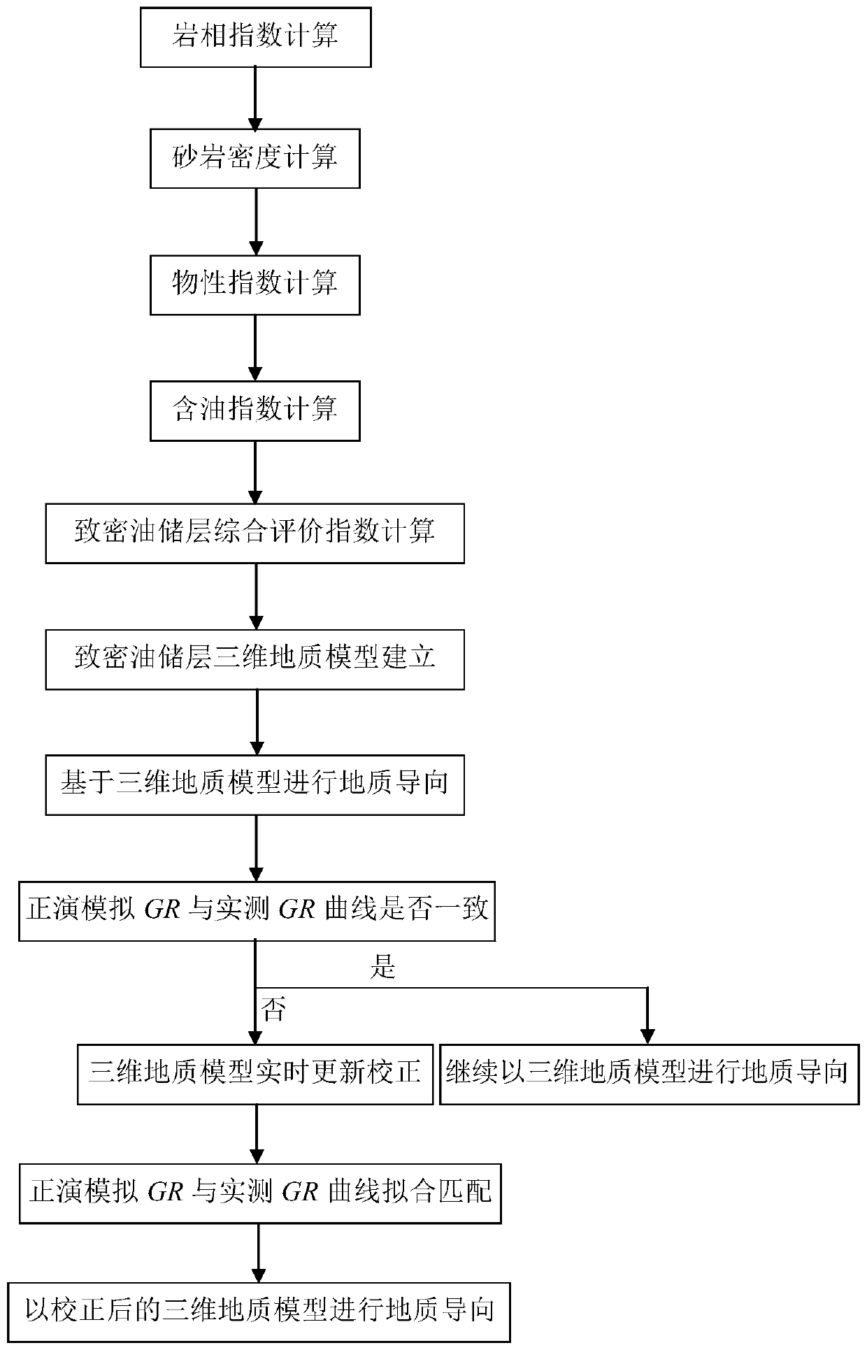
[0029] refer to figure 1 , a method for improving the drilling rate of tight oil reservoirs in horizontal wells, comprising the following steps:

[0030] Step 1. Calculating the lithofacies index: After calculating the relative natural gamma ray based on equation (1) using natural gamma ray logging, use equation (2) to calculate the lithofacies index, and use the lithofacies index to reflect the development characteristics of sandstone and mudstone. details as follows:

[0031]

[0032]

[0033] In the formula: ΔGR is relative natural gamma, dimensionless; GR max 、GR min Respectively, the maximum and minimum values ​​of natural gamma, API; I ltih is the lithofacies index, which is dimensionless; GCUR is the Hirch index, which takes a value of 2 for old strata and 3.7 for new strata, and is dimensionless.

[0034] Step 2. Calculati...


PUM


Abstract

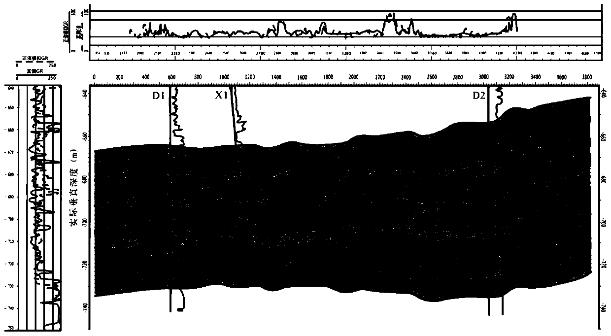
A method for increasing the drilling rate of a tight oil reservoir of a horizontal well comprises the steps that 1, lithofacies indexes are calculated; 2, calculating the sandstone density of the tight oil reservoir; 3, calculating the physical property index of the tight oil reservoir; 4, calculating the oil content index of the tight oil reservoir; step 5, creating a tight oil reservoir comprehensive evaluation index calculation model; step 6, establishing a three-dimensional geological model of the tight oil reservoir; step 7, geoderivation is carried out based on the tight oil reservoir three-dimensional geologic model; 8, updating and correcting the three-dimensional geologic model of the tight oil reservoir in real time, and guiding the drilling direction according to the updated andcorrected three-dimensional geologic model to improve the drilling rate of the tight oil reservoir of the horizontal well; the geological model provided by the invention is closer to real geologicalcharacteristics, and the drilling rate of the tight oil reservoir is further improved.

Description

technical field [0001] The invention belongs to geosteering technology in the development process of tight oil reservoirs, in particular to a method for increasing the drilling rate of tight oil reservoirs in horizontal wells. Background technique [0002] In the process of tight oil development, in order to develop tight oil with high quality and high efficiency, horizontal well development technology must be adopted. How to improve the drilling rate of tight oil reservoirs in horizontal wells is undoubtedly a key technology in the process of tight oil development. Generally speaking, tight oil reservoirs are thick, have good continuity, less muddy interlayers, and good physical properties and oil-bearing properties, so the drilling rate of the reservoir is high; , Poor lateral continuity, well-developed interlayers, and poor physical properties and oil-bearing properties, it is difficult to increase the drilling rate of the reservoir. Existing methods to increase the dri...

Claims


Application Information

Patent Timeline
IPC IPC(8): G06F17/11G06Q10/06G06Q50/02E21B7/04
CPCG06F17/11G06Q10/06393G06Q50/02E21B7/046
Inventor 刘之的杨珺茹时梦璇
Owner XI'AN PETROLEUM UNIVERSITY
Learn More