Magnetic coupling

A magnetic coupling and magnetic pole technology, applied in the direction of permanent magnetic clutch/brake, electric brake/clutch, electrical components, etc., can solve the problems of coupling failure and unfavorable equipment, and achieve convenient processing and transformation and simple structure Effect

Pending Publication Date: 2019-12-03
JIANGSU MAGNET VALLEY TECH
View PDF0 Cites 4 Cited by
  • Summary
  • Abstract
  • Description
  • Claims
  • Application Information

AI Technical Summary

Problems solved by technology

In this slipping process, the magnets of the active permanent magnet rotor and the driven permanent magnet rotor will be demagnetized due to the temperature rise of the eddy current, and the coupling will fail
[0004] Moreover, when "skidding" is accompanied by a certain vibration, it is not good for the equipment

Method used


Image

  • Magnetic coupling
  • Magnetic coupling
  • Magnetic coupling

Examples


Embodiment 1

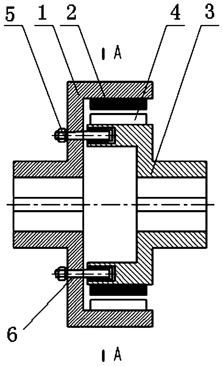
[0051] This embodiment provides a specific implementation of a magnetic coupling, specifically a synchronous cylindrical structure, such as figure 1 As shown, it includes a driving rotor 1, a driven rotor 3 and a connecting structure 5 fixedly arranged on one of the driving rotor 1 and the driven rotor 3, and a connection structure 5 arranged on the driving rotor 1 and the driven rotor 3. The limiting structure on the other of the moving rotor 3.

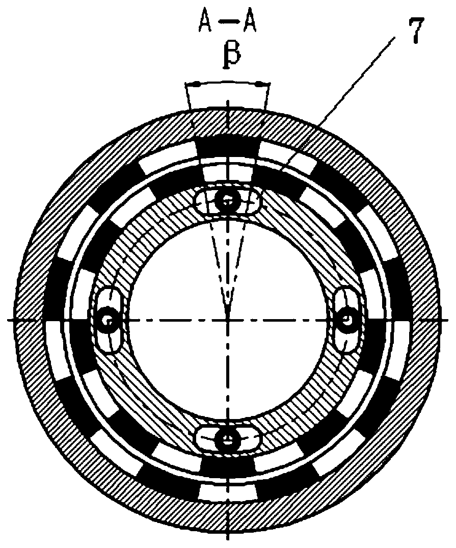
[0052] Wherein the driving rotor 1 is provided with a first permanent magnet 2; the driven rotor 3 is provided with a second permanent magnet 4 that forms a magnetic coupling with the first permanent magnet 2, and the first permanent magnet 2 and the second There is an air gap between the permanent magnets 4 , and the number of magnetic pole pairs of the first permanent magnet 2 and the second permanent magnet 4 is n respectively. Such as figure 2 As shown, the magnetic circuits of the first permanent magnet 2 and the second perm...

Embodiment 2

[0072] This embodiment provides a magnetic coupling with synchronous disc structure, such as Figure 7 with Figure 8 As shown, it includes a driving rotor 1, a driven rotor 3, and a connecting structure 5 fixedly arranged on one of the driving rotor 1 and the driven rotor 3, and a connecting structure 5 arranged on the driving rotor 1 and the driven rotor 3. The limiting structure on the other of the moving rotor 3.

[0073] For the setting of the connecting structure 5 and the limiting structure, refer to the setting of the connecting structure 5 and the limiting structure in the above-mentioned embodiments.


PUM


Abstract

The invention provides a magnetic coupling. The magnetic coupling comprises: a driving rotor which is provided with a first permanent magnet; a driven rotor provided with a second permanent magnet forming magnetic coupling with the first permanent magnet, wherein an air gap is formed between the first permanent magnet and the second permanent magnet, and the number of magnetic pole pairs of the first permanent magnet and the second permanent magnet is n; a connecting structure which is fixedly arranged on one of the driving rotor and the driven rotor and can rotate relative to the driven rotoror the driving rotor; and a limiting structure arranged on the other one of the driving rotor and the driven rotor, wherein the limiting structure enables the rotating angle of the connecting structure relative to the driven rotor or the driving rotor to be smaller than or equal to 180/n degrees. When a load exceeds the maximum magnetic torque capable of being transmitted between the driving rotor and the driven rotor, the connecting structure can provide extra mechanical contact torque force for the driven rotor through the effect of the limiting structure, and the phenomenon of overload slipping when peak load occurs between the driving rotor and the driven rotor can be avoided.

Description

technical field [0001] The invention relates to the technical field of shaft couplings, in particular to a magnetic coupling. Background technique [0002] The magnetic transmission coupling is generally composed of an active permanent magnet rotor and a driven permanent magnet rotor, separated by an isolation cover in the middle, the driven permanent magnet rotor is connected with the driven part, and the active permanent magnet rotor is connected with the power part. The magnets on the active permanent magnet rotor and the driven permanent magnet rotor are composed of permanent magnets magnetized in the radial direction and magnetized in opposite directions. The permanent magnets are arranged alternately along the circumferential direction with different polarities and fixed on the low carbon steel ring. , forming a magnetic disconnection conjoined body. The isolation cover is made of a non-ferritic (and therefore non-magnetic) high-resistance material, typically austenit...

Claims


Application Information

Patent Timeline
Patent Type & Authority Applications(China)
IPC IPC(8): H02K49/10
CPCH02K49/106
Inventor 牟红刚徐俊峰
Owner JIANGSU MAGNET VALLEY TECH
Why Eureka
Try Eureka