Bending forming device of automobile door frame rear door C column
A forming device and door frame technology, which is applied in forming tools, vehicle parts, transportation and packaging, etc., can solve the problems of inner arc wrinkling and depression at the bending place, and achieve the effect of ensuring structural performance and aesthetics
- Summary
- Abstract
- Description
- Claims
- Application Information
AI Technical Summary
Problems solved by technology
Method used
Image

Examples
Embodiment Construction
[0015] The implementation of the present invention will be illustrated by specific specific examples below, and those skilled in the art can easily understand other advantages and effects of the present invention from the contents disclosed in this specification.
[0016] Below in conjunction with accompanying drawing and embodiment the present invention will be further described:
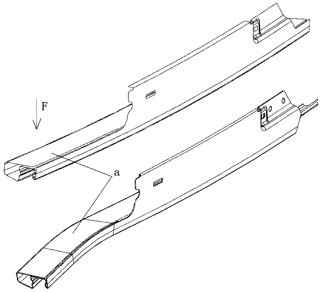
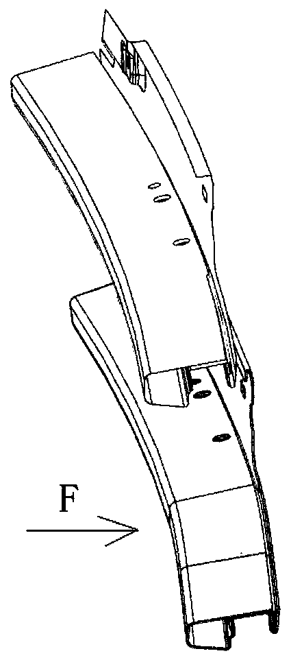
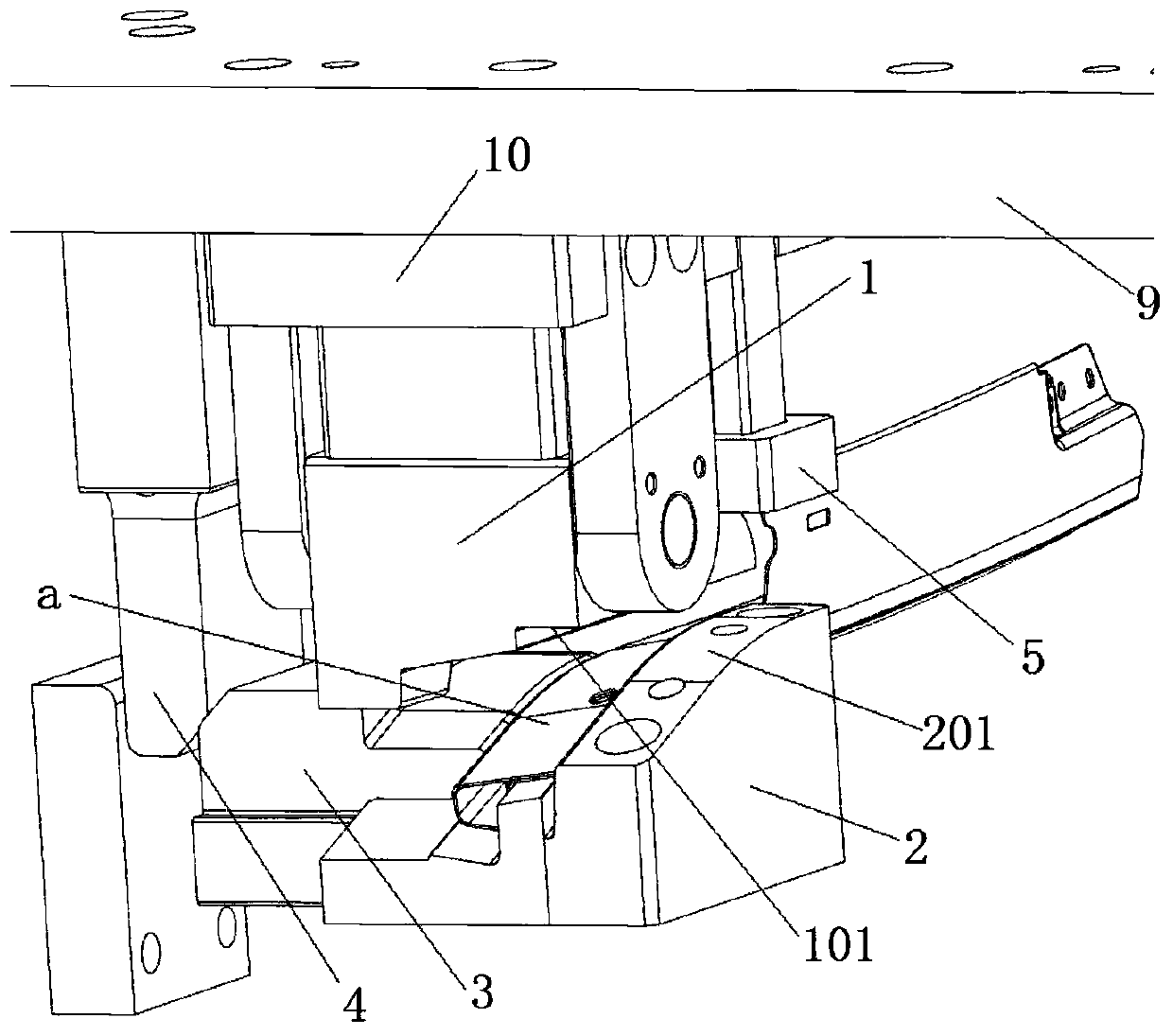
[0017] Such as image 3 -As shown in -6, a kind of bending forming device of the C-pillar of the rear door of the automobile door frame comprises an upper block 1 and a lower block 2, and after the upper block 1 and the lower block 2 are combined, the front end of the C-pillar is pressed into a predetermined shape, the upper block 1 is rotatably installed above the lower block 2 through a hinged structure, and the hinged structure is formed due to the downward movement of the upper block 1 to contact with the C-pillar or lower block 2 to be bent Drive the upper block 1 to rotate downward along the...
PUM
 Abstract
Description
Claims
Application Information