Image forming apparatus and image forming method

a technology of image forming apparatus and forming method, which is applied in the direction of electrographic process apparatus, printing, instruments, etc., can solve the problems of serious degradation of tone characteristics, increase in process time and toner consumption, and inability to produce a uniform tone, etc., to achieve stable forming of toner, good quality, and quick tone correction operation

Inactive Publication Date: 2005-08-23
SEIKO EPSON CORP
View PDF14 Cites 13 Cited by
  • Summary
  • Abstract
  • Description
  • Claims
  • Application Information

AI Technical Summary

Benefits of technology

[0009]A main object of the invention is to provide an image forming apparatus and image forming method for stably forming a toner image of good quality based on a quick tone correction operation featuring high accuracy and consuming a reduced amount of toner.

Problems solved by technology

Unfortunately, the image forming apparatus of this type is susceptible to variations in its characteristics, or particularly the gamma characteristics thereof, in association with environmental changes such as of temperature and humidity or with aging.
Accordingly, a serious degradation of the tone characteristics may result.
Thus, the increase in the number of tone levels to be represented by the patch images results in the increase in process time and toner consumption.
Unfortunately, the density sensor having such a high resolution is expensive.
Furthermore, the reduction of the detection spot size entails increased influences of minor image defects or noises on the detection results so that the detection accuracy is detrimentally lowered.
In addition, more positive detection of the density of the small-sized patch image by means of the density sensor dictates the need for complicated control for high-precision alignment between the patch image and the density sensor.
This also involves a cost increase.
However, the more recent years have seen an increasing user demand for images of higher quality whereas the conventional technique does not necessarily afford the look-up table of sufficient accuracy.
Consequently, the user demand cannot always be satisfied fully.

Method used


Image

  • Image forming apparatus and image forming method
  • Image forming apparatus and image forming method
  • Image forming apparatus and image forming method

Examples


Embodiment Construction

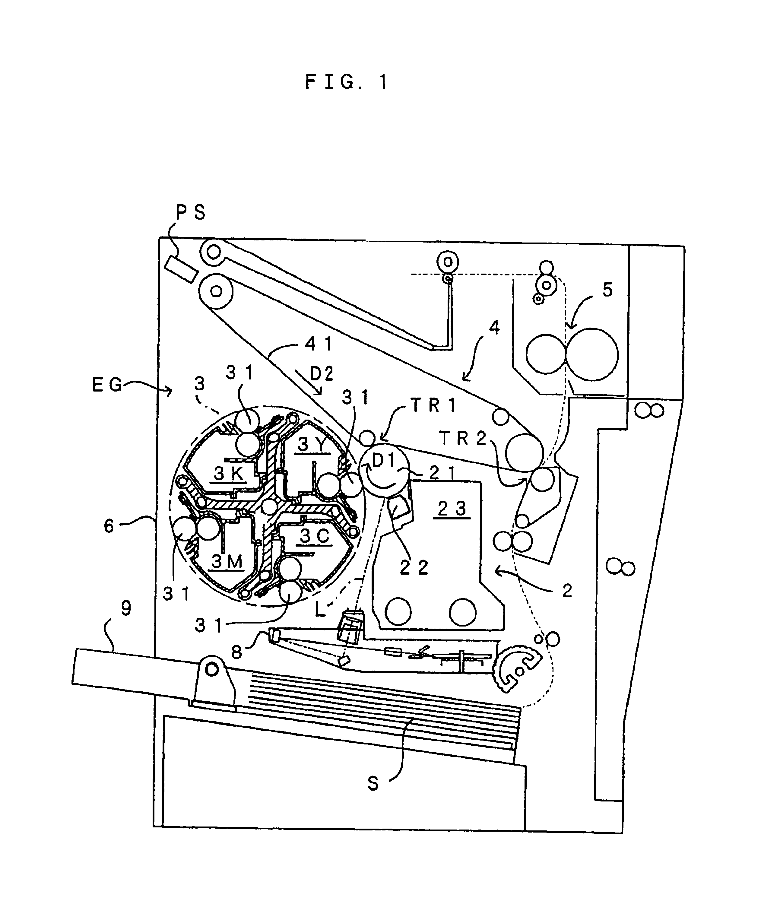
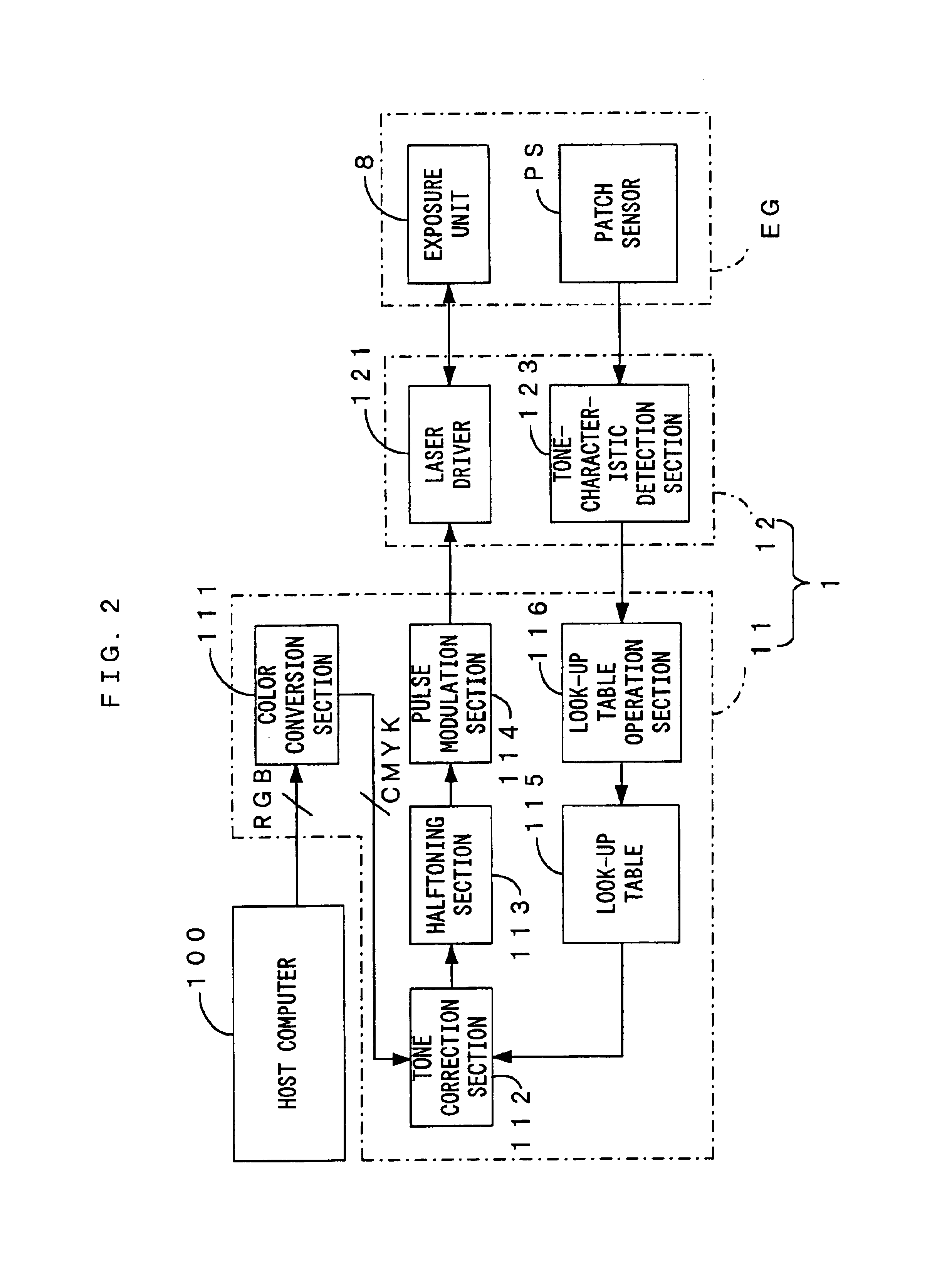
[0022]FIG. 1 is a diagram which shows an image forming apparatus according to one embodiment of the invention, whereas FIG. 2 is a block diagram which shows an electrical arrangement of the image forming apparatus of FIG. 1. The image forming apparatus is adapted to form a full-color image by superimposing toner images of four colors, including yellow (Y), magenta (M), cyan (C) and black (K), on each other or to form a monochromatic image using a black (K) toner alone. The image forming apparatus operates as follows. When an external apparatus such as a host computer 100 supplies an image signal to a main controller 11 of a control unit 1, an engine controller 12 responds to a direction from the main controller 11 so as to control portions of an engine EG whereby an image corresponding to the image signal is formed on a sheet S such as a copy sheet, transfer sheet or transparent sheet for OHP.

[0023]The engine EG includes 7 units: (a) a photosensitive unit 2; (b) a yellow developing ...


PUM


Abstract

A gradation patch image Ip used for determination of tone characteristics of an apparatus is progressively varied in the tone level thereof from the maximum tone level (level 255) to the minimum tone level (level 0). The gradation patch image is either a toner image continuously and consistently varied in the tone level thereof or a toner image having the tone levels varied stepwise at a smaller pitch than a width of a detection region of a patch sensor. In density detection of such a gradation patch image Ip, toner image densities at portions on either sides in the detection region of the patch sensor are canceled each other out by averaging and hence, only a toner image density substantially at the center of the detection region can be obtained.

Description

BACKGROUND OF THE INVENTION[0001]1. Field of the Invention[0002]The present invention relates to an image forming apparatus and image forming method wherein tone correction information is defined based on the density of a formed patch image.[0003]2. Description of the Related Art[0004]As an image forming apparatus such as a printer, a copier and a facsimile, there has been known, for example, an apparatus adapted for optimum color-tone recording by varying the light-emission time of a semiconductor laser based on an image signal sent from a host computer or a scanner. In this apparatus, RGB image signal are converted into CMYK color-tone data for each pixel representing toner colors. Subsequently, with reference to a look-up table stored in a non-volatile memory in the apparatus, the CMYK color-tone data items are corrected for the tone levels thereof based on gamma characteristics of the image forming apparatus (a relationship between a density value indicated by the input image in...

Claims


Application Information

Patent Timeline
Patent Type & Authority Patents(United States)
IPC IPC(8): G03G15/00H04N1/407H04N1/29B41J2/52
CPCH04N1/4078G03G15/5041G03G15/5058G03G2215/00037G03G2215/00063G03G2215/0177
Inventor HAMA, TAKASHI
Owner SEIKO EPSON CORP
Why Eureka
Try Eureka