
Secondary demoulding mechanism with gear and racks for injection mould

A rack-and-pinion and secondary demoulding technology, which is applied in the field of plastic molds, can solve the problems of plastic parts not falling off automatically, potential safety hazards, deformation of plastic parts, etc.

Active Publication Date: 2013-01-09
TAIZHOU KAIHUA AUTOMOBILE MOULD CO LTD
View PDF3 Cites 15 Cited by
  • Summary
  • Abstract
  • Description
  • Claims
  • Application Information

AI Technical Summary

Problems solved by technology

However, after the plastic part is ejected from the core by the stripper plate, the convex ring or edge is still stuck on the stripper plate, and the plastic part cannot fall off automatically, and it needs to be removed manually
Such a demoulding mechanism not only wastes time during mold production, but also increases the labor intensity of operators, and there are certain safety hazards
Moreover, plastic parts are prone to deformation and damage, causing plastic parts to be scrapped

Method used


Image

  • Secondary demoulding mechanism with gear and racks for injection mould
  • Secondary demoulding mechanism with gear and racks for injection mould
  • Secondary demoulding mechanism with gear and racks for injection mould

Examples


Embodiment Construction

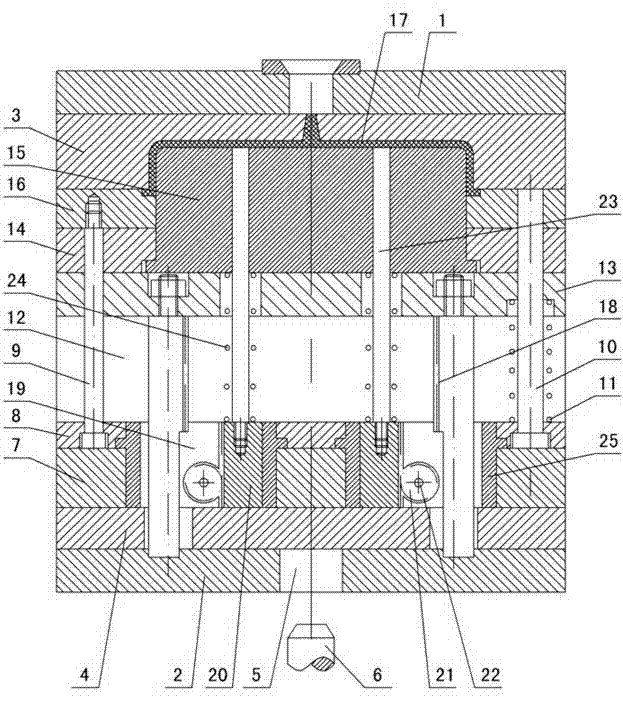
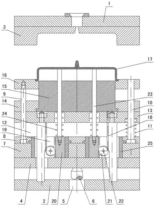
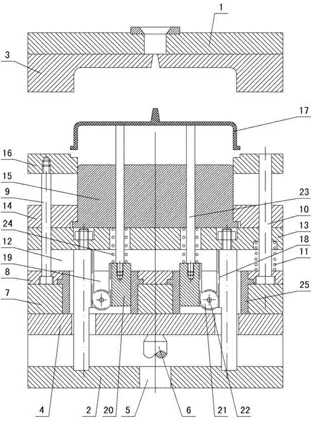
[0010] The invention relates to a rack and pinion secondary demoulding mechanism of an injection mold, such as figure 1 — image 3 As shown, it includes the upper doubler plate 1 and the lower doubler plate 2, the cavity 3 is installed under the upper doubler plate, the ejection support plate 4 is installed on the lower doubler plate 2, the through hole 5 is opened in the lower doubler plate, and the ejector pin 6 of the injection molding machine Pass through the through hole 5 and contact with the bottom of the ejector support plate 4, and the ejector pin push plate 7 and the ejector pin fixed plate 8 are installed on the ejector support plate, and the stripping plate push rod 9 and the reset rod 10 are fixed in the ejector pin fixed plate, and reset A return spring 11 is installed outside the rod, and a mold foot 12 is installed on the lower double plate 2. A support plate 13 is installed on the mold foot. A core fixing plate 14, a core 15 and a stripping plate 16 are instal...


PUM


Abstract

The invention discloses a secondary demoulding mechanism with a gear and racks for an injection mould, comprising an upper compound plate and a lower compound plate, wherein a cavity is installed below the upper compound plate; an ejection support plate is installed on the lower compound plate; a through hole is formed in the lower compound plate; the ejection rod of an injection moulding machine penetrates through the through hole and then contacts with the ejection support plate; an ejection needle pushing plate and an ejection needle fixing plate are installed on the ejection support plate; a stripping plate push rod and a return rod are fixed in the ejection needle fixing plate; a return spring is installed outside the return rod; a mould leg is installed on the lower compound plate; a support plate is installed on the mould leg; a core fixing plate, a core and a stripping plate are installed on the support plate; and a moulded plastic part is arranged among the core, the stripping plate and the cavity. The secondary demoulding mechanism with a gear and racks is characterized in that an acceleration rack is fixed between the lower compound plate and the support plate; installation holes are formed in the ejection needle pushing plate and the ejection needle fixing plate; an ejection needle rack and the gear are installed in the installation holes; the gear is fixed in the ejection needle pushing plate via a rotary shaft; the gear is matched with the acceleration rack and the ejection needle rack respectively; an ejection needle is installed on the ejection needle rack; and the ejection needle penetrates through the core and then contacts with the plastic part.

Description

technical field [0001] The invention relates to a demoulding mechanism of an injection mold, in particular to a secondary demoulding mechanism of a rack and pinion of an injection mold, and belongs to the field of plastic moulds. Background technique [0002] At present, plastic molds are used to produce similar round plastic parts, such as lids, etc., and the bottom surface or outer wall of this type of product is made with a convex ring or edge. Board joint ejection. However, after the plastic part is ejected from the core by the stripper plate, the convex ring or edge is still stuck on the stripper plate, and the plastic part cannot fall off automatically, and it needs to be taken off manually. Such a demoulding mechanism not only wastes time during mold production, but also increases the labor intensity of operators, and there is a certain potential safety hazard. Moreover, the plastic parts are prone to deformation and damage, causing the plastic parts to be scrapped....

Claims


Application Information

Patent Timeline
IPC IPC(8): B29C45/40B29C45/33
Inventor 梁正华
Owner TAIZHOU KAIHUA AUTOMOBILE MOULD CO LTD
Learn More