
Manifold assembling device

A technology for assembling device and sub-catchment, which is applied in metal processing and other directions, can solve the problems of inability to meet production requirements, time-consuming, low processing and assembling efficiency, etc., and achieves the effect of improving assembly and installation efficiency, high degree of automation, and shortening assembly time.

Active Publication Date: 2019-12-06
LINHAI WEIXING NEW BUILDING MATERIALS CO LTD
View PDF5 Cites 2 Cited by
  • Summary
  • Abstract
  • Description
  • Claims
  • Application Information

AI Technical Summary

Problems solved by technology

Most of the existing sub-catchments are PE (Polyethylene pipe, polyethylene plastic) type sub-catchments. When assembling, the pipes need to be manually drilled, and then the joints of the pipes need to be hot-melt welded manually. The processing and assembly efficiency is low. It takes a long time and cannot meet the production demand

Method used


Image

  • Manifold assembling device
  • Manifold assembling device
  • Manifold assembling device

Examples


Embodiment Construction

[0022] The present invention will be further described below in conjunction with the accompanying drawings and specific embodiments, so that those skilled in the art can better understand the present invention and implement it, but the examples given are not intended to limit the present invention.

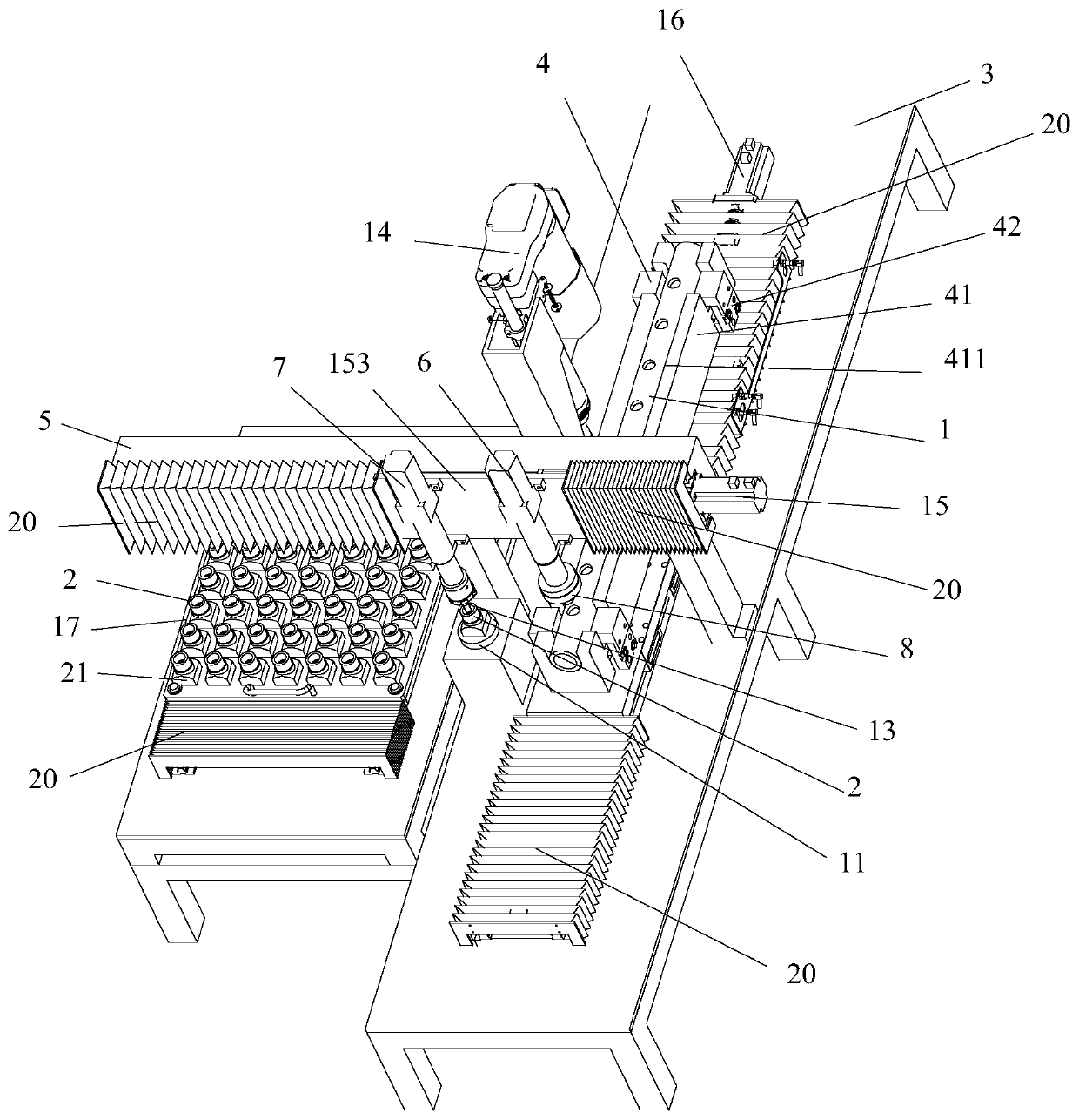
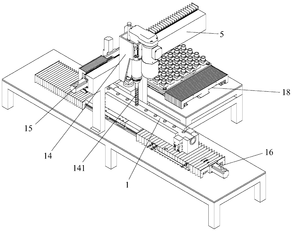
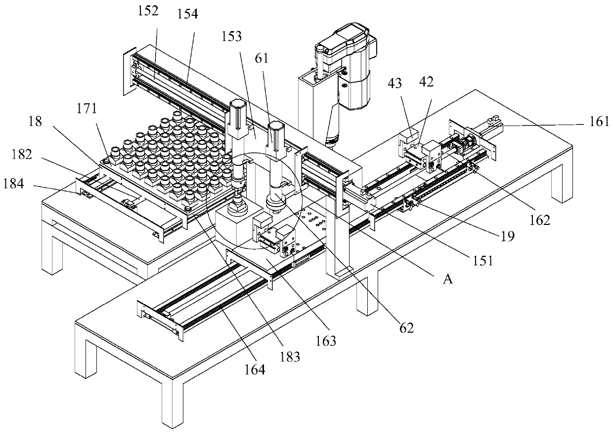
[0023] refer to Figure 1-Figure 5 , this embodiment discloses a sub-catchment assembly device, the sub-collector includes a pipe 1 and a joint 2 connected to the pipe 1, the assembly device includes a frame 3, and the pipe for transporting the pipe 1 is connected to the frame 3 The delivery device 4 and the support arm 5, one side of the support arm 5 is connected with a hot-melt assembly that can move along the length direction of the support arm 5, and the other side is connected with a drilling rig 14 for drilling the pipe 1 delivered by the pipe delivery device 4 , the hot-melt assembly includes a first lifting device 6 and a second lifting device 7, the first lifting device ...


PUM


Abstract

The invention discloses a manifold assembling device. A manifold comprises a pipe and a connector connected to the pipe. The assembling device comprises a rack, wherein a pipe delivering device and asupporting arm are connected to the rack; a hot melting component which can move along the length direction of the supporting arm is connected to one side of the supporting arm; a drilling rig is connected to the other side of the supporting arm; the hot melting component comprises a first lifting device and a second lifting device; a first heating element for heating the pipe is connected to thefirst lifting device; a clamping jaw for grabbing the connector is connected to the second lifting device; a transfer board is also connected to the rack; and a second heating element for heating theconnector is connected to the transfer board. The manifold assembling device disclosed by the invention can effectively improve the assembling and installing efficiency, is high in automatic degree and shortens the assembling time.

Description

technical field [0001] The invention relates to the technical field of pipeline processing, in particular to a water collector assembly device. Background technique [0002] The sub-catchment is a water flow distribution and collection device composed of a water collector and a water divider. The water divider is used to disperse one way of water into multiple outputs, and the water collector is used to combine multiple ways of water into one. output all the way. Most of the existing sub-catchments are PE (Polyethylene pipe, polyethylene plastic) type sub-catchments. When assembling, the pipes need to be manually drilled, and then the joints of the pipes need to be hot-melt welded manually. The processing and assembly efficiency is low. It takes a long time and cannot meet the production demand. Contents of the invention [0003] The technical problem to be solved by the present invention is to provide a sub-catchment assembly device, which can effectively improve the ef...

Claims


Application Information

Patent Timeline
IPC IPC(8): B29C65/18B29C65/78B26F1/16
CPCB29C65/18B29C65/78B29C66/522B29C66/80B26F1/16
Inventor 厉恩贵叶德园马德耿
Owner LINHAI WEIXING NEW BUILDING MATERIALS CO LTD
Learn More