
Bin-separation-type truck carriage self-dumping structure

A technology of self-unloading and compartments, which is applied in the direction of freight vehicles, motor vehicles, and vehicles with push plates, etc. It can solve the problems of vehicle rollover, difficult to control the center of gravity, wheel obstruction, etc., to solve the problem of starting difficulties, Effects of avoiding position deviation and improving safety

Pending Publication Date: 2019-12-06
成都创奇汽车制造有限公司
View PDF0 Cites 6 Cited by
  • Summary
  • Abstract
  • Description
  • Claims
  • Application Information

AI Technical Summary

Problems solved by technology

One is the way of sideways tipping, but it is easy to lose balance, and the center of gravity is not easy to control when the truck is unloading, which may cause safety accidents of vehicle rollover
Another is to set the unloading mechanism inside the carriage, but it is easy to occupy a large space, and because it is a long carriage, the entire unloading mechanism is difficult to operate; moreover, there are often gaps in the unloading mechanism, and fine materials are leak from the gap
Moreover, these two unloading methods will cause materials to accumulate at the wheels and wrap the wheels. When the vehicle starts to drive again, the materials will hinder the wheels, making it difficult to start.
In order to solve the problem of wheel stacking, some companies design unloading guide plates and other methods, but the structure is complex and requires manual assistance to complete, which is very inconvenient
[0005] It is precisely because of such or such defects that similar designs are rare in the market now

Method used


Image

  • Bin-separation-type truck carriage self-dumping structure
  • Bin-separation-type truck carriage self-dumping structure
  • Bin-separation-type truck carriage self-dumping structure

Examples


Embodiment Construction

[0033] The present invention will be further described below in conjunction with the accompanying drawings, but the protection scope of the present invention is not limited to the following description.

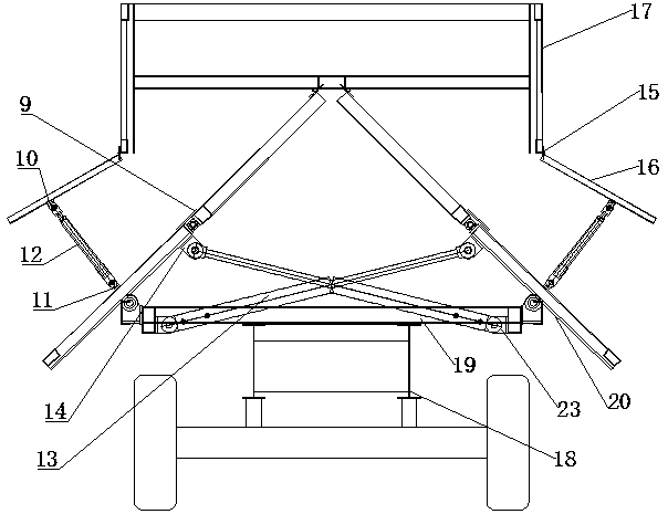
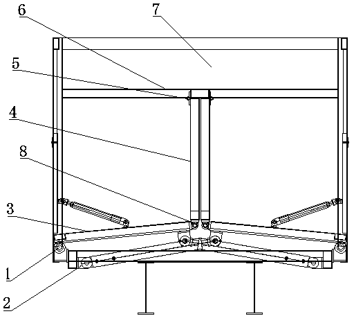
[0034] Such as figure 1 As shown, the self-unloading structure of the sub-compartment truck compartment is provided with a bottom beam 19 on the frame 18, the compartment body 17 is placed on the cross beam 19, and the compartment interior 7 of the compartment body 17 is provided with a self-unloading structure.

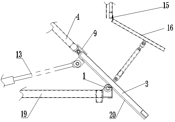
[0035] In the carriage body 17, there are many material compartments 21 arranged along the front-rear direction, and the both sides of the material compartment 21 are hinged with side doors 16 through door hinges 15 (such as image 3 , Figure 4 with Figure 5 shown). Each feed compartment 21 is provided with a self-unloading structure. Preferably, the compartments are separated by partitions 24 to form material compartments 21 .

[0036] The self-unloading str...


PUM


Abstract

The invention relates to a bin-separation-type truck carriage self-dumping structure. The bin-separation-type truck carriage self-dumping structure comprises bending pushing plate mechanisms and sealing soft belts; the bending pushing plate mechanisms are symmetrically arranged in the cavity of a carriage; each symmetrical side comprises a bottom pushing plate and a side pushing plate which are hinged to each other; during contraction, the side pushing plates cling to each other, and the bottom pushing plates cling to the bottom surface of the carriage to form a large space; during extension,the bottom pushing plates extend out of the carriage from the side directions so that materials are prevented from being accumulated at wheels; and the sealing soft belts are arranged at clearances atthe hinge parts of the bending pushing plate mechanisms, so that the materials are prevented from being leaked. The bin-separation-type truck carriage self-dumping structure has the beneficial effects that the inner space is large; dumped materials are not accumulated at the wheels; fine materials are not leaked; motion is simple; and safety is high.

Description

technical field [0001] The invention relates to the technical field of automatic unloading of trucks, in particular to a warehouse-type self-unloading structure for truck compartments. Background technique [0002] In trucks with self-unloading function, hydraulic ejector rods are commonly used to realize this function. [0003] The most common thing in life is that the rear of the carriage is hinged, and a hydraulic jack is set under the front of the carriage, such as mine cars and tractors. However, for some trucks with long carriages, this design cannot be adopted. This is because the length of the carriages is long. To completely unload the cargo, there must be a large enough elevation angle, which requires the hydraulic jack to be long enough. If the length is too long, it will It is easy to cause it to be bent during the jacking process. Therefore, in daily life, trucks with longer compartments often use manual unloading. [0004] It is not convenient to manually un...

Claims


Application Information

Patent Timeline
IPC IPC(8): B60P1/00
CPCB60P1/006
Inventor 邹仁松张良福童治群胡万军杜华强
Owner 成都创奇汽车制造有限公司
Learn More