Hydraulic automatic control flow limiting sewage intercepting gate device

A hydraulic automatic control and gate technology, which is applied to water supply devices, waterway systems, drainage structures, etc., can solve problems such as slow movement, need to use electricity, and expensive products

Pending Publication Date: 2019-12-06
杜曲
View PDF0 Cites 2 Cited by
  • Summary
  • Abstract
  • Description
  • Claims
  • Application Information

AI Technical Summary

Problems solved by technology

Although the role of the swirl flow limiting valve can make the rise of the water level in the interception well not significantly increase the rain and sewage mixed water entering the sewage outlet, the product is expensive, and the model of the product must be determined by UFT using a specially developed computer program. Sure
[0006] 3. Some sewage interception wells are equipped with floating balls (or buoys) with convex bottoms to form hydraulic self-control sewage interception gates. During heavy rains, when the water level in the sewage interception wells rises to a certain position, the gates of the sewage outlets are completely closed. During the process, due to the slow action when the water level in the interception well is low, there is a problem that the amount of water entering the sewage outlet far exceeds the design interception flow
Although the device has the characteristics of accurate current limiting, it needs to use electricity, and the product is expensive

Method used


Image

  • Hydraulic automatic control flow limiting sewage intercepting gate device
  • Hydraulic automatic control flow limiting sewage intercepting gate device
  • Hydraulic automatic control flow limiting sewage intercepting gate device

Examples


Embodiment Construction

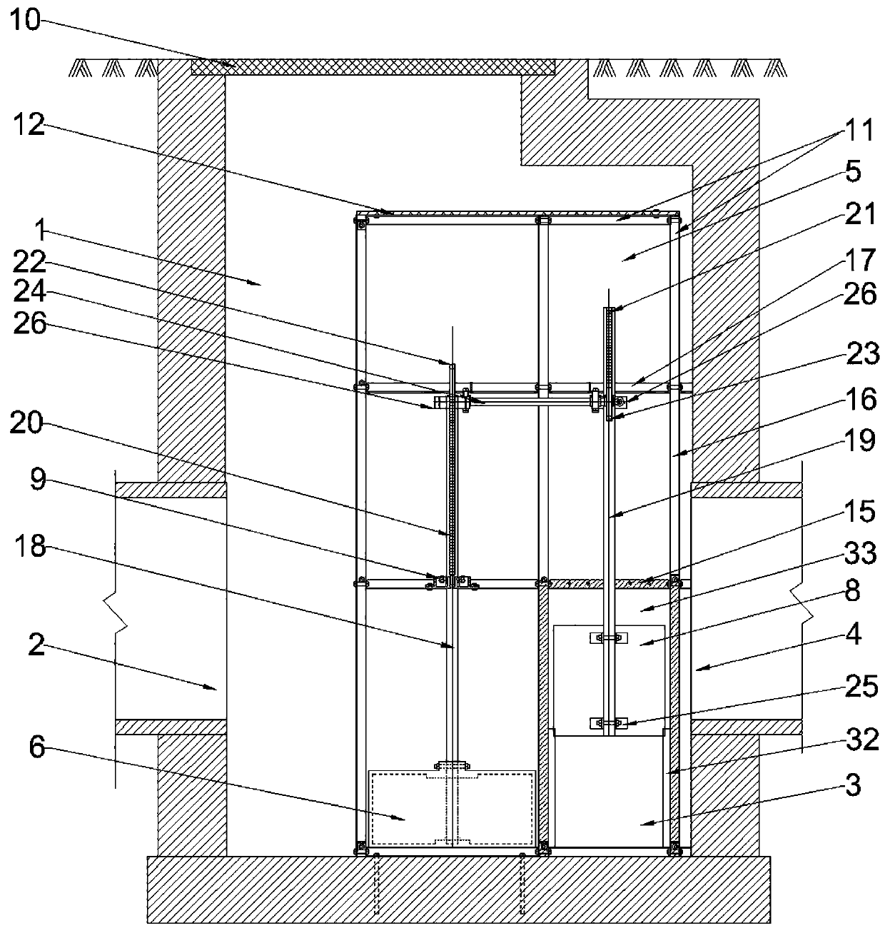
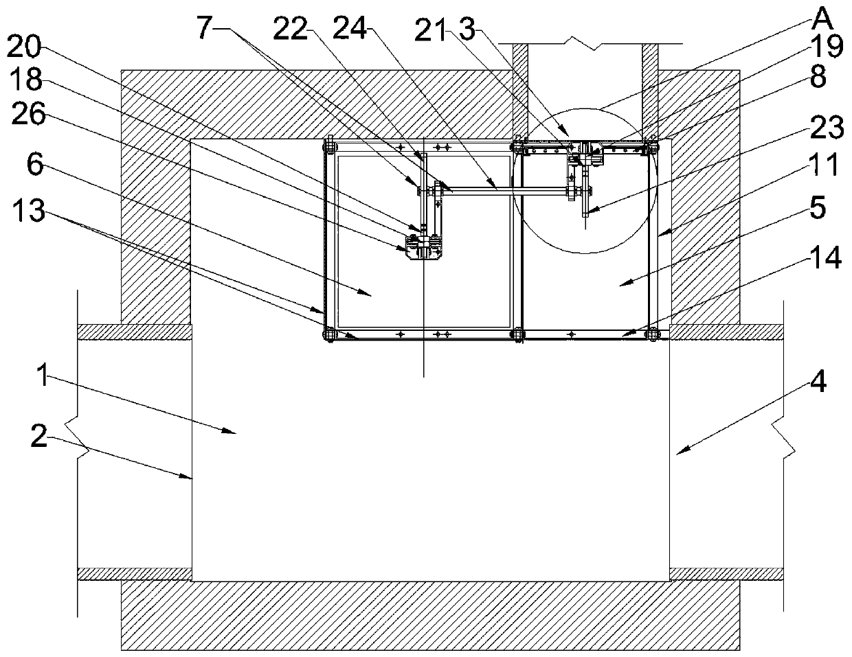
[0034] Such as figure 1 and figure 2 As shown, in this embodiment, the hydraulic self-controlled flow-limiting sewage interception gate 8 device is arranged in the sewage interception well 1, and the water inlet 2 of the sewage interception well 1 is connected to the combined drainage pipe, and the sewage interception The sewage outlet 3 of the well 1 is connected to the sewage pipe, and the flood outlet 4 of the sewage interception well 1 is connected to the downstream river or pipeline. The hydraulic self-controlled flow-limiting sewage interception gate device includes a sluice chamber 5 and is installed in the sluice. The buoyancy tank 6 on the flat bottom of the chamber 5, the transmission assembly 7 and the gate 8, the buoyancy tank 6 is connected to the gate 8 through the transmission assembly 7, and the gate 8 controls the amount of sewage discharged from the sewage outlet 3 , and the movement direction of the buoyant tank 6 is opposite to that of the gate 8, and the...


PUM


Abstract

The invention aims at providing a hydraulic automatic control flow limiting sewage intercepting gate device which is reasonable in design, precise in flow limiting and low in manufacturing cost. The hydraulic automatic control flow limiting sewage intercepting gate device is arranged on a sewage draining exit in a sewage intercepting well, and comprises a gate chamber, a flat-bottom-face buoyancychamber, a transmission assembly, a gate and a limiting sleeve for limiting the buoyancy chamber to float upwards within the allowable range, and the flat-bottom-face buoyancy chamber, the transmission assembly, the gate and the limiting sleeve are arranged in the gate chamber. The buoyancy chamber with the flat bottom face is adopted, the drinking water depth of the buoyancy chamber is reduced, under the condition that the water in the gate chamber is shallow, the gate can be driven in time through the transmission assembly, the opening height of the gate can be automatically controlled, theeffect of precisely limiting the amount of water flowing into the sewage draining exit during rain falling can be achieved, through the limiting sleeve, in the period of intense fall, the gate has theminimum opening height, and the design of precise flow limiting without cut off is achieved. The device is applied to the technical field of reasonable water making and draining.

Description

technical field [0001] The invention relates to the technical field of combined drainage, in particular to a hydraulic self-controlled flow-limiting sewage interception gate device. Background technique [0002] The combined system is a drainage method that uses the same pipeline to collect and transport rainwater and domestic sewage, and it is also a drainage method that causes water environment pollution. Therefore, sewage interception measures should be taken, but there are many problems in the current interception wells and their devices, which seriously affect Pollution interception effect. [0003] The existing problems of intercepting wells and devices thereof are: [0004] 1. Ordinary sewage interception wells are not equipped with flow-limiting sewage interception devices. During the rainstorm, the mixed rainwater and sewage entering the sewage outlet will continue to increase with the rise of the water level in the sewage interception well, often far exceeding th...

Claims


Application Information

Patent Timeline
Patent Type & Authority Applications(China)
IPC IPC(8): E03F5/04E03F7/02
CPCE03F5/0401E03F7/02
Inventor 杜曲皮凌华杜佐道杜娟
Owner 杜曲
Why Eureka
Try Eureka