
Wear-resisting ball valve capable of resisting high temperature and high pressure

A technology of high temperature and high pressure resistance, applied in the field of wear-resistant ball valves, can solve the problems of mechanical wear, high friction of ball valve parts, poor wear resistance, etc., and achieve the effects of improving service life, ensuring accuracy and high temperature resistance

Active Publication Date: 2019-12-06
JIANG SU YAN DIAN FA MEN CO LTD
View PDF5 Cites 5 Cited by
  • Summary
  • Abstract
  • Description
  • Claims
  • Application Information

AI Technical Summary

Problems solved by technology

[0003] However, the existing oil and gas use ball valves to control the following problems in the transportation process. a. The existing ball valves are mainly made of metal materials. The friction between the parts of the ball valve is large, and frequent use is prone to mechanical wear, which makes the ball valve unable to work normally. b. The ball valve When transporting gas, the airtightness is required to be high, and the existing ball valves are easy to damage the airtightness due to wear and tear during use, and the wear resistance is poor, which is easy to cause oil and gas leakage, and there are potential safety hazards
[0004] Regarding some problems of ball valves in oil and gas transportation operations, related industries have made research and proposed specific technical solutions, such as a Chinese utility model patent with a patent number of 2017207069825, which improves the structure of the lower valve stem. wear, which effectively improves the phenomenon of torque increase after the ball valve is frequently opened. However, some of the problems mentioned above about the ball valve in oil and gas transmission operations have not been involved.

Method used


Image

  • Wear-resisting ball valve capable of resisting high temperature and high pressure
  • Wear-resisting ball valve capable of resisting high temperature and high pressure
  • Wear-resisting ball valve capable of resisting high temperature and high pressure

Examples


Embodiment Construction

[0026] The embodiments of the present invention will be described in detail below with reference to the accompanying drawings, but the present invention can be implemented in many different ways defined and covered by the claims.

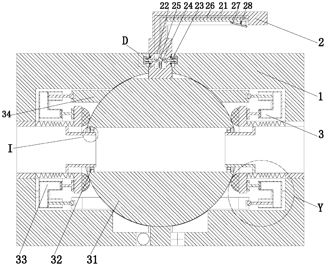
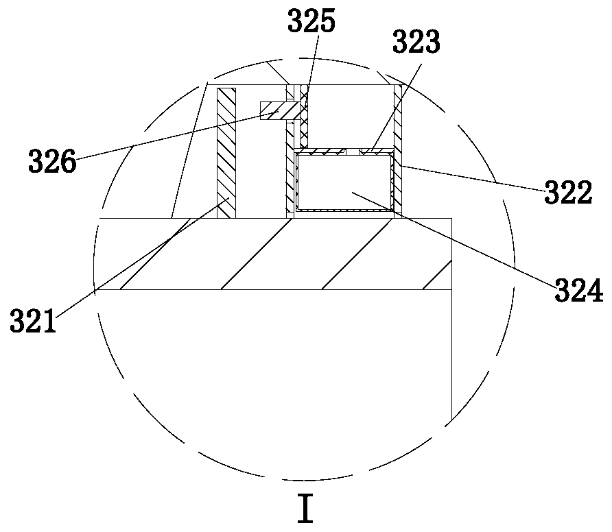
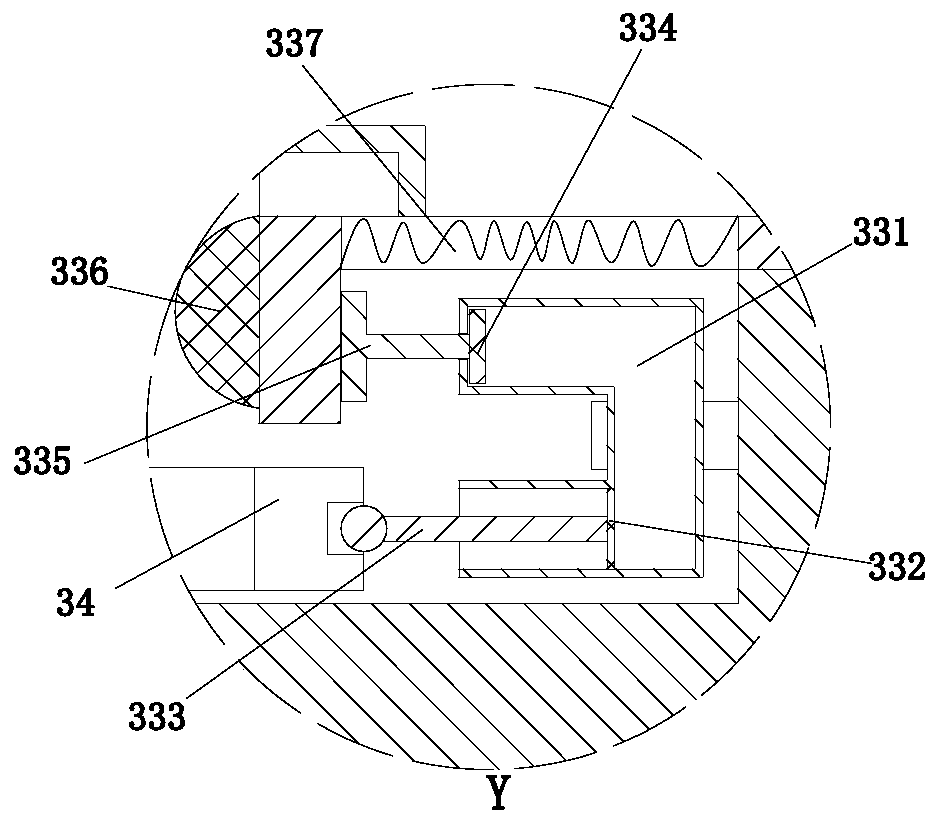
[0027] Such as Figure 1 to Figure 5 As shown, a wear-resistant ball valve that can withstand high temperature and high pressure includes a valve body 1, a control hole is opened on the upper end of the valve body 1, a control assembly 2 is arranged in the control hole, and an actuator assembly 3 is installed on the lower end of the control assembly 2. The actuator assembly 3 is arranged in the valve body 1 .

[0028] The control assembly 2 includes a control rod 21 installed on the execution ball 31, the control rod 21 is located in the control hole, the control rod 21 is provided with a threading chamber, the lower end of the control rod 21 is provided with a control chamber 22, the threading chamber and the control chamber 22 Unicom, the outer w...


PUM


Abstract

The invention relates to a wear-resisting ball valve capable of resisting high temperature and high pressure. The wear-resisting ball valve comprises a valve body. A control hole is formed in the upper end of the valve body. A control assembly is arranged in the control hole. An execution assembly is mounted at the lower end of the control assembly and is arranged in the valve body. According to the wear-resisting ball valve, the following problems that in the existing process of controlling the conveying process of oil gas through a ball valve, the existing ball valve is mainly made of a metal material, friction force between ball valve parts is large, mechanical wear is prone to happening due to frequent use, consequently, the ball valve cannot be used normally, the requirement for sealing performance is high when the ball valve conveys gas, during use of the existing ball valve, airtightness is prone to being damaged after wear, wear resistance is poor, oil gas leaking is prone to being caused, and potential safety hazards exist can be solved.

Description

technical field [0001] The invention relates to the technical field of oil and gas valve transportation, in particular to a wear-resistant ball valve capable of high temperature and high pressure. Background technique [0002] Petroleum and natural gas are important material resources in our country. It is a relatively common way to use pipelines to utilize and transport oil and natural gas. Valves installed on pipelines can effectively control the effect of oil and gas transportation, and the use of valves directly affects the oil and gas. Safety in conveying operations. [0003] However, the existing oil and gas use ball valves to control the following problems in the transportation process. a. The existing ball valves are mainly made of metal materials. The friction between the parts of the ball valve is large, and frequent use is prone to mechanical wear, which makes the ball valve unable to work normally. b. The ball valve When transporting gas, the airtightness is req...

Claims


Application Information

Patent Timeline
Patent Type & Authority Applications(China)
IPC IPC(8): F16K5/06F16K5/20F16K35/02
CPCF16K5/0647F16K5/0689F16K5/205F16K35/025
Inventor 赵波季明生张群
Owner JIANG SU YAN DIAN FA MEN CO LTD
Learn More