A multi-channel ultrasonic flowmeter transducer drive circuit and control method thereof
A driving circuit and ultrasonic technology, applied in computer control, program control, general control system, etc., can solve the problems of high GPIO driving capability, reduced system reliability, affecting the sound of ultrasonic transducers, etc., to eliminate the need for simulation The effect of switching switches, reduction of driving power requirements, and avoidance of switching noise
- Summary
- Abstract
- Description
- Claims
- Application Information
AI Technical Summary
Problems solved by technology
Method used
Image
Examples
Embodiment 1
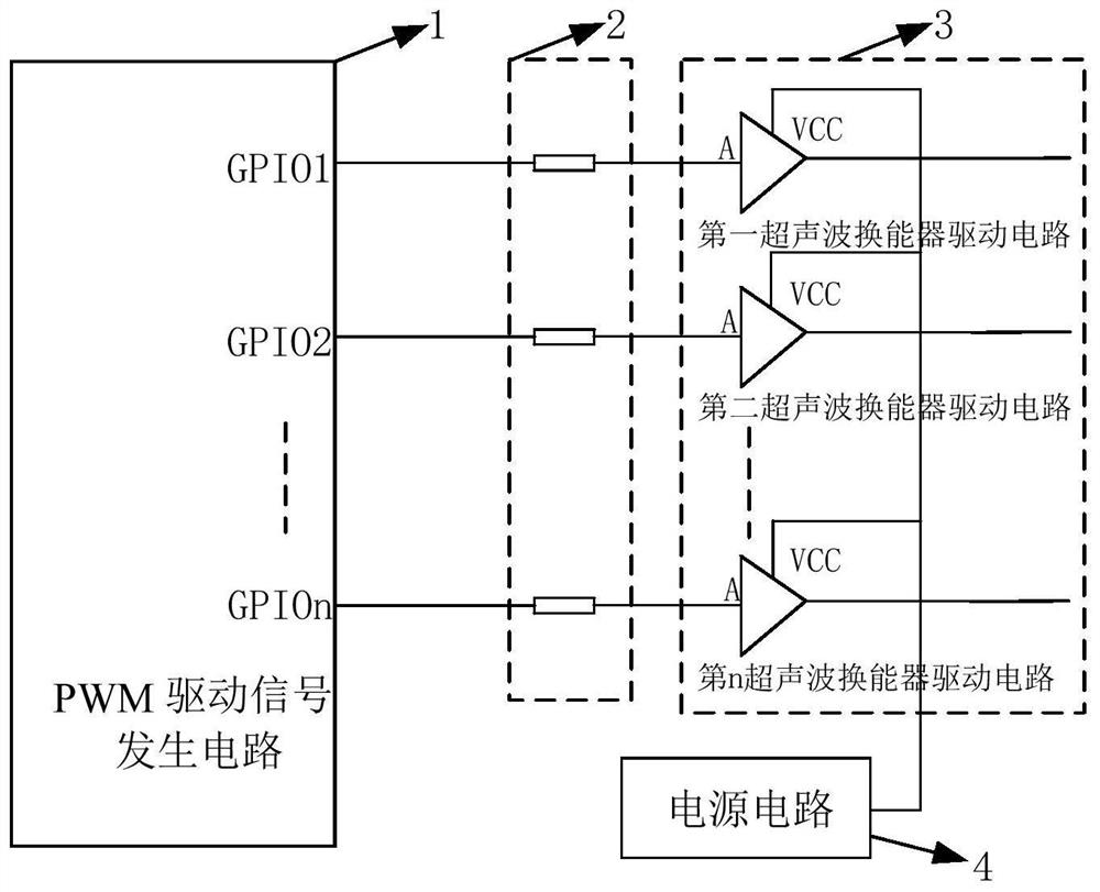
[0030] see figure 1 As shown, the present invention provides a multi-channel ultrasonic flowmeter transducer driving circuit, including a PWM driving signal generating circuit 1, the PWM driving signal generating circuit 1 includes a plurality of GPIO ports, and each GPIO port outputs one PWM signal respectively Each PWM signal is connected to the control terminal of one ultrasonic transducer drive circuit 3 through the current limiting resistor 2; the ultrasonic transducer drive circuit 3 is connected to the power supply circuit 4.
[0031] Further, see figure 2 As shown, the PWM driving signal generation circuit 1 includes an MCU controller 5, and a plurality of said GPIO ports are located on the MCU controller 5; The PWM signal is generated under the control of the MCU controller 5; the MCU controller 5 also includes a plurality of output channels 7 connected to the PWM timer 6, and the plurality of output channels 7 are connected to the output channel controller 8, and e...
Embodiment 2
[0045] see figure 1 As shown, the present invention provides a multi-channel ultrasonic flowmeter transducer driving circuit, wherein the number of channels is n / 2, and two ultrasonic transducers are arranged in one channel, which requires two ultrasonic transducers to drive The circuit includes a PWM driving signal generating circuit 1, a current limiting resistor 2 connected to the PWM driving signal generating circuit, an ultrasonic transducer driving circuit 3 connected to the current limiting resistor 2, and a power supply for providing power to the ultrasonic transducer driving circuit 3 Circuit 4. The PWM driving signal generating circuit 1 outputs multiple PWM signals, and each PWM signal is respectively connected to the control terminal of the ultrasonic transducer driving circuit 3 through the current limiting resistor 2; the output terminal of the ultrasonic transducer driving circuit 3 outputs ultrasonic transducer The output end of the power supply circuit 4 is c...
PUM
 Abstract
Description
Claims
Application Information
 - R&D
- Intellectual Property
- Life Sciences
- Materials
- Tech Scout
- Unparalleled Data Quality
- Higher Quality Content
- 60% Fewer Hallucinations
Browse by: Latest US Patents, China's latest patents, Technical Efficacy Thesaurus, Application Domain, Technology Topic, Popular Technical Reports.
© 2025 PatSnap. All rights reserved.Legal|Privacy policy|Modern Slavery Act Transparency Statement|Sitemap|About US| Contact US: help@patsnap.com


