
A Design Method of Adjustable Electrical Thickness Fitting Reflection Test Waveguide Probe

A reflection test and design method technology, applied in the test field, can solve the problems that the reflection coefficient phase cannot reflect IPD monotonously, restrict the direct application of the reflection method, etc., and achieve a good measurement linearity effect

Active Publication Date: 2021-08-17
THE 41ST INST OF CHINA ELECTRONICS TECH GRP
View PDF10 Cites 0 Cited by
  • Summary
  • Abstract
  • Description
  • Claims
  • Application Information

AI Technical Summary

Problems solved by technology

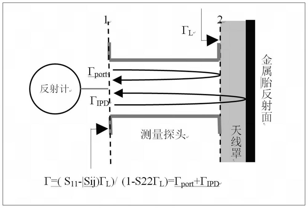
[0005] Due to the double mutation of the electromagnetic wave transmission medium and the waveguide structure, there is often a serious mismatch between the waveguide probe of the microwave reflectometer and the outer wall of the radome, and it is difficult to satisfy Γ in most engineering applications. IPD Intensity greater than Γ port As a result, the measured reflection coefficient phase cannot reflect the change of IPD monotonously, which seriously restricts the direct application of reflection method in electrical thickness measurement.

Method used


Image

  • A Design Method of Adjustable Electrical Thickness Fitting Reflection Test Waveguide Probe
  • A Design Method of Adjustable Electrical Thickness Fitting Reflection Test Waveguide Probe

Examples


Embodiment Construction

[0024] Below in conjunction with accompanying drawing and specific embodiment the present invention is described in further detail:

[0025] A method for designing waveguide probes with adjustable electrical thickness for reflection testing, comprising the following steps:

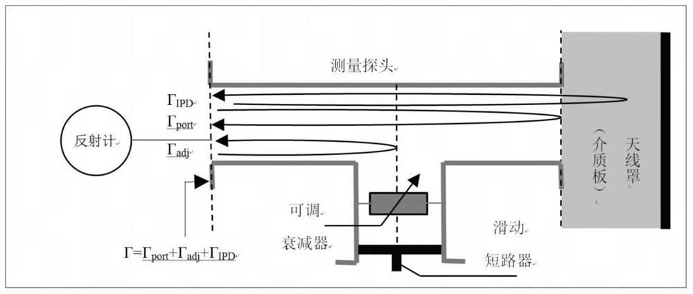
[0026] Step 1: Add a parallel stub to the test waveguide to form a three-port microwave network structure, such as figure 2 As shown, the parallel stubs include adjustable attenuators and sliding shorts, and the parallel stubs will introduce an additional reflection coefficient component Γ adj , the role of the parallel branch is to adjust Γ adj , making it the same as Γ port Equivalent inversion, so that Γ adj with Γ port cancel each other out, making Γ close to Γ IPD ;

[0027] Step 2: Connect the port of the test waveguide (such as the right port) to the dielectric plate of the same material as the radome with the electrical thickness to be tested;

[0028] Step 3: Set the attenuation of the adj...


PUM


Abstract

The invention discloses a design method of an adjustable electric thickness fitting reflection testing waveguide probe, which belongs to the technical field of testing. The invention adds adjustable reflection coefficient components to the traditional reflection type electric thickness measurement waveguide probe by adding parameter-adjustable waveguide branches, and can adjust and cancel the mismatch reflection between the probe and the outer surface of the radome for a specific working frequency. Only the contribution of the IPD reflection signal is retained in the reflection coefficient of , which solves the engineering application problem of the reflection type electric thickness measurement method, and provides a good measurement linearity.

Description

technical field [0001] The invention belongs to the technical field of testing, and in particular relates to a design method of a waveguide probe for adjustable electric thickness lamination reflection testing. Background technique [0002] Electric thickness refers to the increase in wave number relative to the vacuum path of the same geometric size when the electromagnetic wave radiation passes through the non-vacuum medium space, which can be equivalent to the phase delay of the electromagnetic wave propagating in the medium relative to the vacuum increase, called insertion phase delay (IPD) . The IPD parameter is of great significance to the design of the radome and must be measured during the fabrication process. The traditional IPD test is to place the radome under test between the microwave transceiver antennas, and measure the transmission phase difference caused by different radome for comparative measurement, or compare it with the transmission phase without placi...

Claims


Application Information

Patent Timeline
Patent Type & Authority Patents(China)
IPC IPC(8): G01R29/10G01B7/06
CPCG01B7/06G01R29/10
Inventor 郭利强吴强冷朋
Owner THE 41ST INST OF CHINA ELECTRONICS TECH GRP
Learn More