
Flame cutting torch position adjusting device

A technology for adjusting devices and cutting torches, which is applied in the direction of gas flame welding equipment, welding equipment, metal processing equipment, etc., can solve the problems of unable to meet the requirements of bending angle bevel processing, single processing function, and low bevel accuracy, and achieve operation Fast, improve processing efficiency, simple operation effect

Inactive Publication Date: 2019-12-10
XINCHANG BINGYIN INTELLIGENT TECH CO LTD
View PDF0 Cites 0 Cited by
  • Summary
  • Abstract
  • Description
  • Claims
  • Application Information

AI Technical Summary

Problems solved by technology

[0002] At present, most of the flame cutting torches of CNC cutting machines are fixed, and the processing function is single; even if the adjustable flame cutting torch is generally used, it can only be adjusted up and down or left and right. When moving, it relies on manual movement to cut in a straight line. , but cannot meet the processing requirements of bending angle grooves
Moreover, due to the influence of low precision when the machine adjusts the angle of the cutting nozzle, the accuracy of the cut groove is not high. Flame cutting torch adjustment device

Method used


Image

  • Flame cutting torch position adjusting device
  • Flame cutting torch position adjusting device
  • Flame cutting torch position adjusting device

Examples


Embodiment Construction

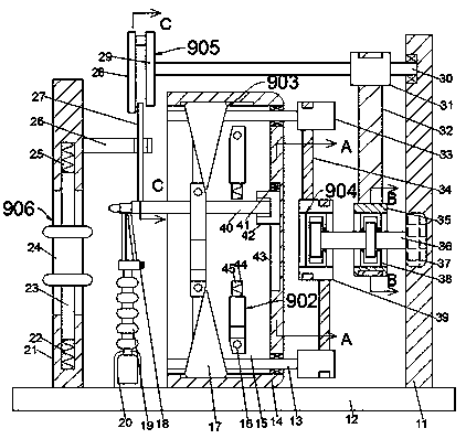
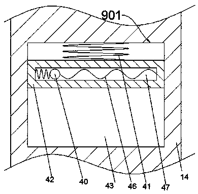
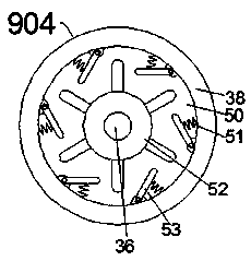
[0023] Combine below Figure 1-Figure 6 The present invention is described in detail, and for convenience of description, the orientations mentioned below are now stipulated as follows: figure 1 The up, down, left, right, front and back directions of the projection relationship itself are consistent.

[0024] The invention relates to a flame cutting torch position adjustment device, which is mainly used in the process of making "V" or "U" grooves on steel plates. The invention will be further described below in conjunction with the drawings of the invention:

[0025] A flame cutting torch position adjustment device according to the present invention includes a base 12, and a working box 14 is fixed on the upper end surface of the base 12, and a transmission chamber 15 with an opening to the left is arranged inside the working box 14. The inner wall on the right side of the transmission chamber 15 is provided with a lifting groove 43, and a moving device 901 is slidably connec...


PUM


Abstract

The invention discloses a flame cutting torch position adjusting device. The device comprises a base, a work box is fixedly arranged on the end face of the upper side of the base, a transmission cavity with a leftward opening is formed in the work box, a lifting groove is formed in the inner wall of the right side of the transmission cavity, a moving device is in sliding connection to the liftinggroove, the moving device comprises a lifting block in sliding connection to the lifting groove, a transverse moving groove formed in the lifting block, and a guide sliding rod in sliding connection with the transverse moving groove. A rail plate in a letter shape is used for limiting a nozzle moving part, the nozzle partial moving path communicates with the letter shape, a V-shaped or U-shaped conventional bending groove is formed in a steel plate, the low precision of manual moving is avoided, meanwhile, the splicing manner is adopted in the rail part, free switching of machining needs can be achieved, operation is easy, running is rapid, and machining efficiency is improved.

Description

technical field [0001] The invention relates to the technical field of thermal cutting equipment, in particular to a flame cutting torch position adjustment device. Background technique [0002] At present, most of the flame cutting torches of CNC cutting machines are fixed, and the processing function is single; even if the adjustable flame cutting torch is generally used, it can only be adjusted up and down or left and right. When moving, it relies on manual movement to cut in a straight line. , but it cannot meet the processing requirements of bending angle grooves. Moreover, due to the influence of low precision when the machine adjusts the angle of the cutting nozzle, the accuracy of the cut groove is not high. Flame cutting torch adjustment device. Contents of the invention [0003] technical problem: [0004] Because the flame cutting torch of the CNC flame cutting machine moves in a straight line, it is very inconvenient when beveling on the steel plate, and can...

Claims


Application Information

Patent Timeline
Patent Type & Authority Applications(China)
IPC IPC(8): B23K7/10
CPCB23K7/102
Inventor 吴玉钿
Owner XINCHANG BINGYIN INTELLIGENT TECH CO LTD
Learn More