

Crane and crane control method
A crane and jib technology, applied in the field of crane and crane control, can solve problems such as low precision
- Summary
- Abstract
- Description
- Claims
- Application Information
AI Technical Summary
Problems solved by technology
Method used
Image

Examples
Embodiment Construction
[0047] The following will clearly and completely describe the technical solutions in the embodiments of the present invention with reference to the accompanying drawings in the embodiments of the present invention. Obviously, the described embodiments are only some, not all, embodiments of the present invention. The following description of at least one exemplary embodiment is merely illustrative in nature and in no way taken as limiting the invention, its application or uses. Based on the embodiments of the present invention, all other embodiments obtained by persons of ordinary skill in the art without creative efforts fall within the protection scope of the present invention.
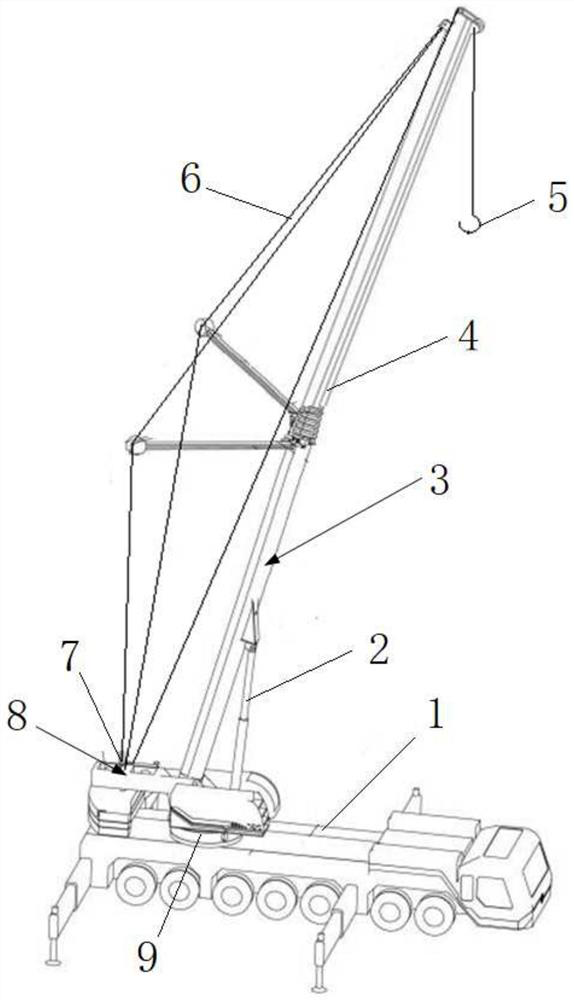
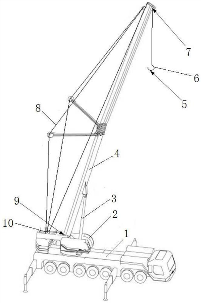
[0048] to combine figure 2 with 3As shown, in this embodiment, the crane includes a bearing part 2, a boom 4, a hook 6, a winch system 14, a positioning system and a controller. The lifting arm 4 is mounted on the carrying part 2 in a pitch-swingable manner and includes an arm head located at an e...
PUM
 Abstract
Description
Claims
Application Information