Novel pressure gauge joint

A pressure gauge, a new type of technology, applied in the direction of measuring fluid pressure, measuring devices, instruments, etc., can solve the problems of inconvenient disassembly, blocked pressure gauge inlet, pipeline welding slag, etc., to achieve convenient installation and disassembly, prevent liquid leakage, prevent The effect of clogging

Inactive Publication Date: 2019-12-10
江苏林诚电仪设备有限公司
View PDF1 Cites 2 Cited by
  • Summary
  • Abstract
  • Description
  • Claims
  • Application Information

AI Technical Summary

Problems solved by technology

[0002] A pressure gauge refers to an instrument that uses elastic elements as sensitive elements to measure and indicate pressure higher than the environment. It is widely used. It is used in almost all industrial processes and scientific research fields. Fields such as maintenance factories and stores can be seen everywhere. The pressure gauge joint is a connecting piece connecting the pressure gauge and the pipeline. In the prior art: the patent of the authorized publication number CN 207050912 U discloses a kind of antifreeze pressure gauge joint, including the joint body. A joint sleeve connected to the pipeline is threaded inside the joint body, and a liquid storage chamber communicated with the head of the pressure gauge is provided in the joint body, and antifreeze is provided in the liquid storage chamber, and the slippage A working piston is provided, and the working piston penetrates the joint sleeve to contact with the antifreeze, an extension plate is provided on the outer side wall of the working piston close to the antifreeze liquid, and a limiter that conflicts with the extension plate is provided on the inner side wall of the liquid storage chamber. The bit plate is usually connected to the pipeline by welding. During the welding process, it is easy to generate welding slag inside the pipeline, which is inconvenient to clean and disassemble. Once the pipeline is adjusted and changed, the pipeline welded with the pressure gauge joint will be damaged. If it cannot be restored, it is not applicable and can only be scrapped, resulting in waste. In addition, without a filter device, it is easy to cause impurities inside the pipeline to block the inlet of the pressure gauge, which is inconvenient to clean. When the pressure gauge is locked, the direction is not easy to adjust, and it is inconvenient to observe. Therefore, we propose a new type of pressure gauge joint to solve the above defects

Method used


Image

  • Novel pressure gauge joint
  • Novel pressure gauge joint
  • Novel pressure gauge joint

Examples


Embodiment Construction

[0027] The following will clearly and completely describe the technical solutions in the embodiments of the present invention with reference to the accompanying drawings in the embodiments of the present invention. Obviously, the described embodiments are only some, not all, embodiments of the present invention. Based on the embodiments of the present invention, all other embodiments obtained by persons of ordinary skill in the art without making creative efforts belong to the protection scope of the present invention.

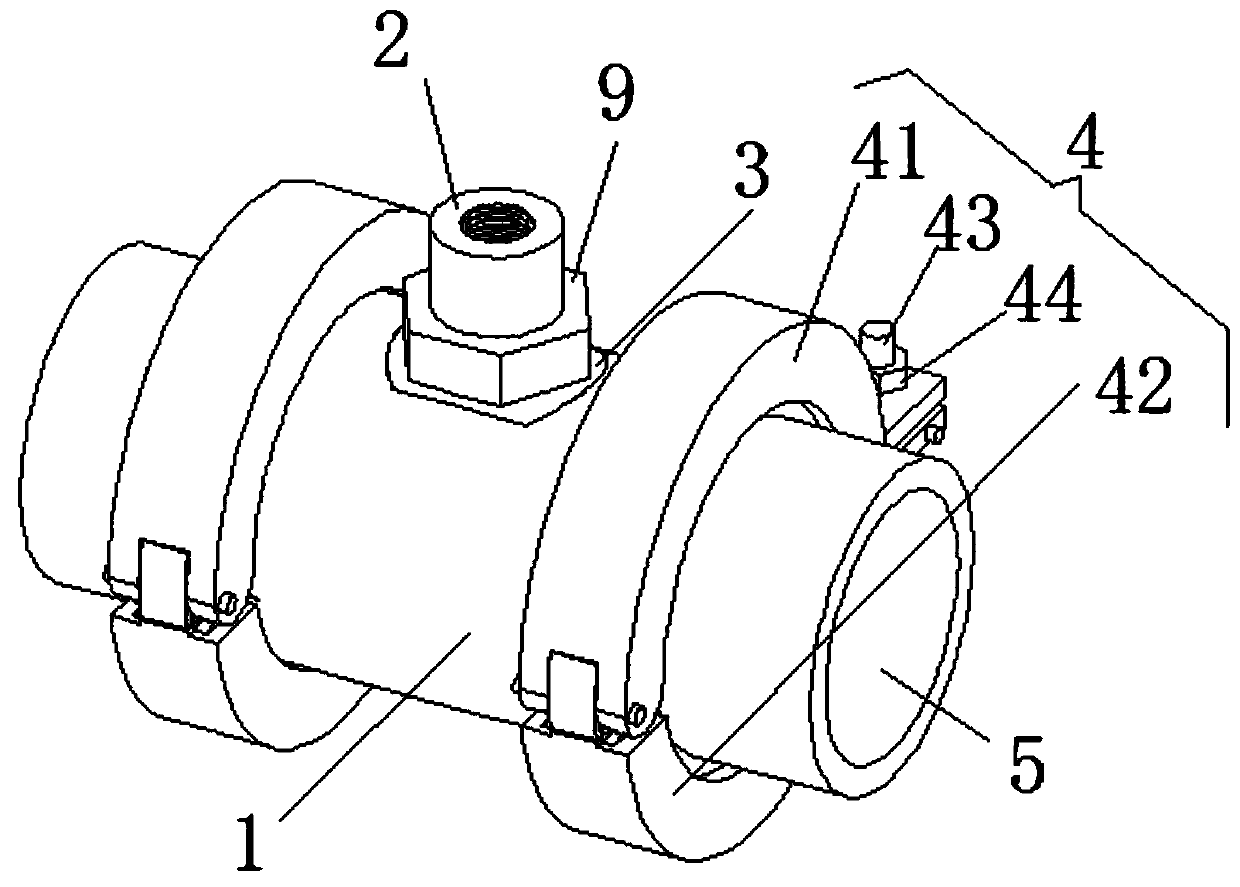
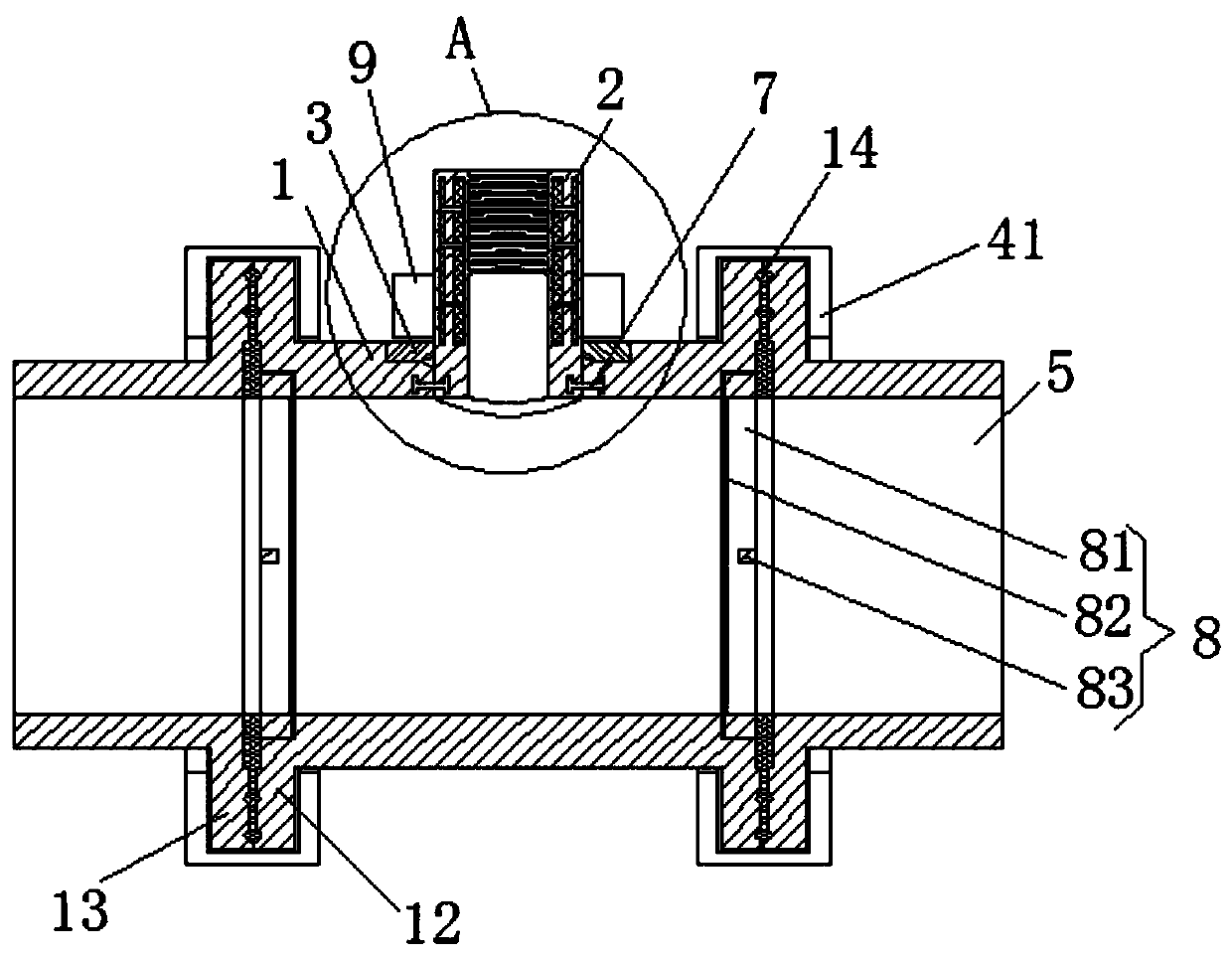
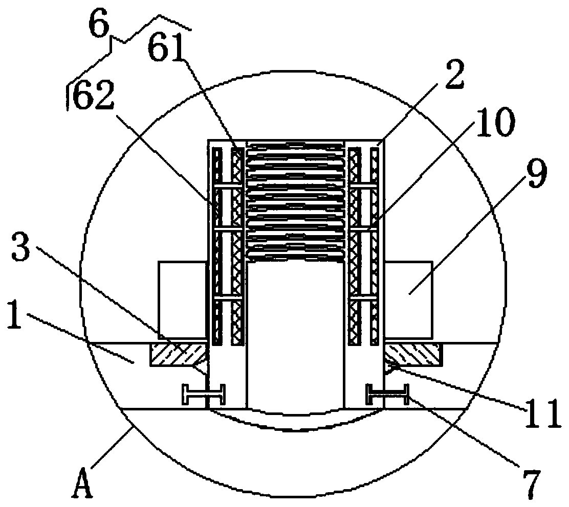
[0028] see Figure 1-3 , the present invention provides a technical solution: a new type of pressure gauge joint, including a connecting pipe 1, a joint body 2, a quick buckle 4, an antifreeze unit 6 and a filter unit 8;

[0029] Connecting pipe 1: both ends of the connecting pipe 1 are fixedly connected with the first flange 12, and the middle part of the arc surface of the connecting pipe 1 is provided with a through hole;

[0030] Joint body 2: The outer a...


PUM


Abstract

The invention discloses a novel pressure gauge joint. The pressure gauge joint comprises a connecting pipe, a joint body, quick buckles, an anti-freezing unit and a filtering unit. The two ends of theconnecting pipe are fixedly connected with first flanges; a through hole is formed in the middle of the cambered surface of the connecting pipe; a limiting ring is fixedly connected to the outer arcsurface of the lower end of the joint body; the lower end of the joint body is rotationally connected with the through hole of the connecting pipe arc surface; the lower side face of the limiting ringmakes contact with the upper end slope of the through hole of the connecting pipe; the quick buckle is arranged outside the first flanges; the anti-freezing unit is arranged in the side wall of the joint body; the filtering unit is arranged at the end of the connecting pipe. The novel pressure gauge joint also includes a fixing plate, and the fixing plate is arranged at the upper end of the though hole of the connecting pipe. The pressure gauge joint is convenient to disassemble, can be recycled, avoids waste, is provided with the filtering device, avoids the situation that impurities in a pipeline block an inlet of a pressure gauge, and is convenient to clean, convenient to adjust the direction of the pressure gauge and convenient to observe.

Description

technical field [0001] The invention relates to the technical field of pressure gauges, in particular to a novel pressure gauge joint. Background technique [0002] A pressure gauge refers to an instrument that uses elastic elements as sensitive elements to measure and indicate pressure higher than the environment. It is widely used. It is used in almost all industrial processes and scientific research fields. Fields such as maintenance factories and stores can be seen everywhere. The pressure gauge joint is a connecting piece connecting the pressure gauge and the pipeline. In the prior art: the patent of the authorized publication number CN 207050912 U discloses a kind of antifreeze pressure gauge joint, including the joint body. A joint sleeve connected to the pipeline is threaded inside the joint body, and a liquid storage chamber communicated with the head of the pressure gauge is provided in the joint body, and antifreeze is provided in the liquid storage chamber, and t...

Claims


Application Information

Patent Timeline
IPC IPC(8): G01L19/00G01L19/06
CPCG01L19/0007G01L19/06G01L19/0636
Inventor 奚陈俊
Owner 江苏林诚电仪设备有限公司
Why Eureka
Try Eureka