Eureka AIR delivers breakthrough ideas for toughest innovation challenges, trusted by R&D personnel around the world.

Reaction cavity

A reaction chamber and chamber technology, applied in the field of reaction chambers, can solve problems affecting the distribution of reaction gases, damage to the intake duct 1, and thread jamming, etc., to achieve the effect of improving uniformity and avoiding damage

Active Publication Date: 2019-12-10
BEIJING NAURA MICROELECTRONICS EQUIP CO LTD
View PDF7 Cites 0 Cited by
  • Summary
  • Abstract
  • Description
  • Claims
  • Application Information

AI Technical Summary

Problems solved by technology

[0004] However, due to the small contact area between the upper end of the bolt 4 and the horizontal part of the intake duct 1, this may cause the intake duct 1 to tilt and slide relative to the bolt 4, resulting in a change in the outlet position of the intake duct 1, thereby affecting the reaction The distribution of gas in the reaction chamber, and when the bolt 4 is used to adjust the intake duct 1 or the intake duct 1 tilts and slides, the horizontal part of the intake duct 1 and the bolt 4 are prone to breakage, causing the intake air The damage of conduit 1 and the high temperature in the reaction chamber are prone to thread jamming or loosening, affecting the normal adjustment function of the bolt 4 to the intake conduit 1, resulting in a decrease in efficiency and an increase in cost

Method used


Image

  • Reaction cavity
  • Reaction cavity
  • Reaction cavity

Examples


Embodiment Construction

[0040] In order to enable those skilled in the art to better understand the technical solution of the present invention, the reaction chamber provided by the present invention will be described in detail below with reference to the accompanying drawings.

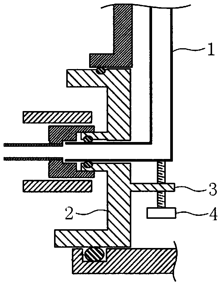
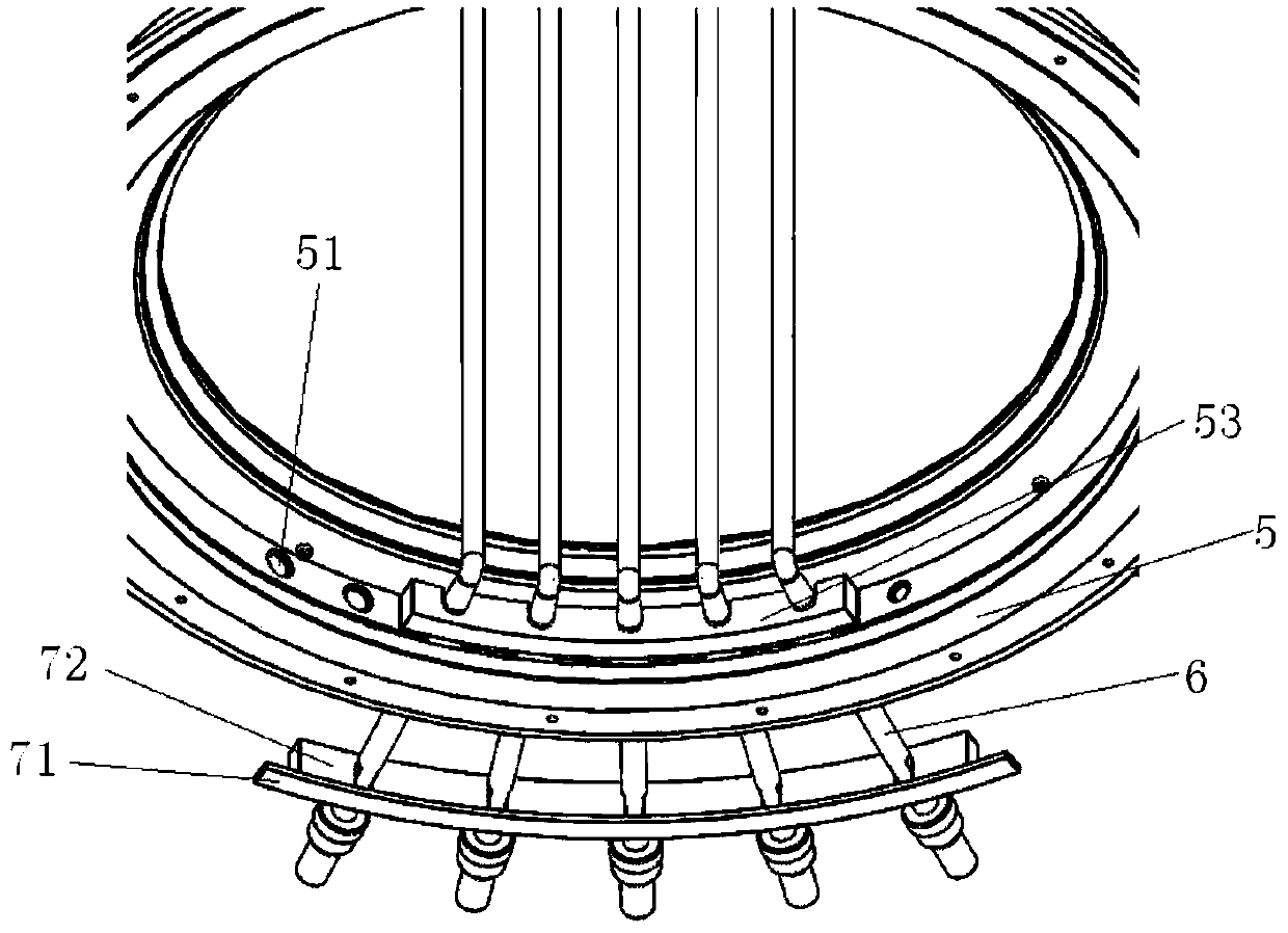
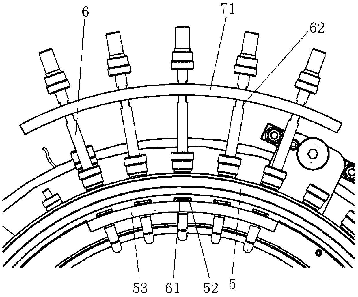
[0041] Such as Figure 2-Figure 7 As shown, the present invention provides a reaction chamber, which includes: a cavity 5, an inlet pipe 6, a first limiting structure, a second limiting structure and a third limiting structure. Wherein, a through hole 51 is provided in the cavity 5 . The air intake pipe 6 extends into the cavity 5 through the through hole 51 . The first limiting structure is arranged inside the cavity 5; the second limiting structure is arranged on the intake pipe 6, and cooperates with the first limiting structure to limit the axial rotation and radial translation of the intake pipe 6; the second limiting structure The three limiting structures are connected with the cavity 5 and cooperate with the second...


PUM


Abstract

The invention provides a reaction cavity. The reaction cavity comprises a cavity body where a through hole is formed, a gas inlet pipe extending into the cavity through the through hole, a first limiting structure arranged on an inner side of the cavity, a second limiting structure which is arranged on the gas inlet pipe and matched with the first limiting structure so as to limit axial rotation and radial translation of the gas inlet pipe, and a third limiting structure which is connected with the cavity and matched with the second limiting structure so as to limit radial rotation and axial translation of the gas inlet pipe. The reaction cavity is advantaged in that the gas inlet pipe can be fixed stably, so distribution uniformity of reaction gas in the reaction cavity can be improved, and the gas inlet pipe is not easy to damage.

Description

technical field [0001] The invention relates to the technical field of semiconductor heat treatment equipment, in particular to a reaction chamber. Background technique [0002] At present, semiconductor heat treatment equipment is an important process equipment for integrated circuit manufacturing. It mainly includes a reaction chamber and an inlet pipe. The reaction gas enters the reaction chamber through the inlet pipe and reacts with the semiconductor parts to be processed, thereby performing heat treatment on the semiconductor parts to be processed. processing. Among them, the outlet position of the inlet pipe will directly affect the distribution of the reaction gas in the reaction chamber, and the uniformity of the distribution of the reaction gas in the reaction chamber will affect the process performance of semiconductor heat treatment, and because the temperature in the reaction chamber is high and the metal Elements will have a great impact on the performance of ...

Claims


Application Information

Patent Timeline
Patent Type & Authority Applications(China)
IPC IPC(8): H01L21/67
CPCH01L21/67098
Inventor 杨帅董金卫杨慧萍
Owner BEIJING NAURA MICROELECTRONICS EQUIP CO LTD
Why Eureka
Eureka Blog
Learn More