Small submersible pond sludge sucking device

A submersible, pond technology, used in earthmovers/shovels, mechanically driven excavators/dredgers, construction, etc., can solve problems such as troublesome implementation, slow equipment work, inconvenient movement in water, etc., to avoid blockages Sludge pump, the effect of reducing the diffusion area and reducing the turbidity

Inactive Publication Date: 2019-12-13
安徽知库云端科技服务有限公司
View PDF0 Cites 1 Cited by
  • Summary
  • Abstract
  • Description
  • Claims
  • Application Information

AI Technical Summary

Problems solved by technology

[0004] Aiming at the deficiencies of the prior art, the present invention provides a small-scale submersible pond dredging device, which has a small volume and flexible work, and can directly enter the bottom of the water for dredging work, and can also flexibly move underwater to realize Efficient and fast decontamination work and other advantages solve the problems of high pond desilting cost, slow equipment work and long construction period, inconvenient water movement, poor desilting effect and troublesome implementation

Method used


Image

  • Small submersible pond sludge sucking device
  • Small submersible pond sludge sucking device
  • Small submersible pond sludge sucking device

Examples


Embodiment 1

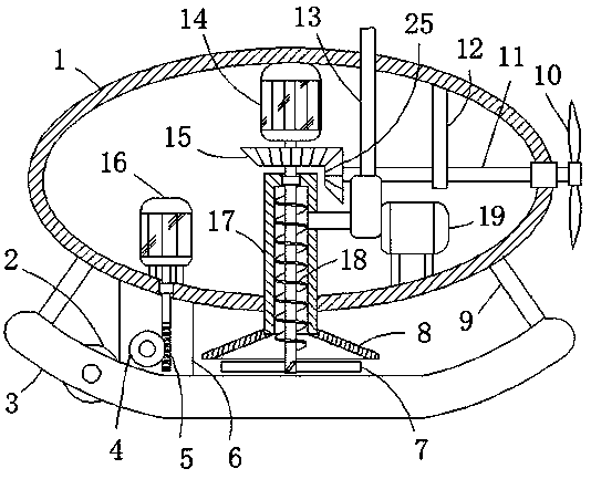
[0023] Embodiment 1: A small-sized submersible pond suction device, including a sludge pump 19 and a housing 1 with an arc-shaped structure. The center of the inner wall of the lower end of the housing 1 is fixedly connected with a fixed block 17 through a mounting hole, and the lower end of the fixed block 17 is opened. There is a cylindrical groove, and a stirring structure is arranged in the cylindrical groove. The input end of the sludge pump 19 is fixedly connected with a connecting pipe, and one side of the fixed block 17 is fixedly connected with the nozzle of the connecting pipe through a round hole, and the connecting pipe communicates with the cylindrical groove , the upper end of the housing 1 is fixedly connected with an output pipe 13 through a through hole, the lower end of the output pipe 13 passes through the through hole and is fixedly connected with the output end of the sludge pump 19, and the power input end of the sludge pump 19 is connected through a wire a...

Embodiment 2

[0025] Embodiment 2: the difference based on Embodiment 1 is;

[0026] The agitating mechanism includes a rotating shaft arranged in the cylindrical groove, the upper end of the rotating shaft is rotationally connected with one side of the cylindrical groove through the second sealed bearing, the shaft wall of the rotating shaft is fixedly connected with a helical blade 18, and the inner wall of the upper end of the housing 1 is fixed The first motor 14 is connected, and the power input end of the first motor 14 is electrically connected to the external power supply through wires and control switches. This technology has been widely used in daily life, and those skilled in the art should know it, so it will not be done again. More details, the end of the output shaft of the first motor 14 passes through the first sealed bearing and is fixedly connected with the upper end of the rotating shaft, the output shaft of the first motor 14 is fixedly connected with the second bevel gea...

Embodiment 3

[0029] Embodiment 3: the difference based on embodiment 1 is;

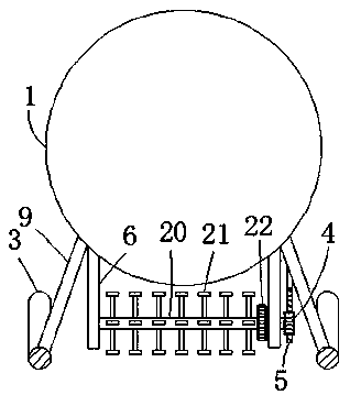
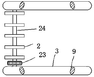
[0030]The pulverizing mechanism includes a stirring shaft 20 which is rotatably connected between the two mounting plates 6 through a first rolling bearing. The shaft wall of the stirring shaft 20 is fixedly connected with a plurality of evenly distributed crushing blades 21, and the plurality of crushing blades 21 are T-shaped. structure, one end of the stirring shaft 20 passes through the first rolling bearing and is fixedly connected with the worm wheel 4, the worm wheel 4 is meshed with the worm 5, the upper end of the worm 5 is rotationally connected with the lower side of the housing 1 through the third sealed bearing, the housing 1 The inner wall of the lower end is fixedly connected with a second motor 16, and the power input end of the second motor 16 is electrically connected with an external power supply through a wire and a control switch. To repeat too much, the output end of the second motor 16 passe...


PUM


Abstract

The invention relates to the technical field of pond dredging and discloses a small submersible pond sludge sucking device. The small submersible pond sludge sucking device comprises a sludge pump anda shell of an arc structure. A fixing block is fixedly connected to the center position of the inner wall of the lower end of the shell through an installation hole, and a cylinder groove is formed in the lower end of the fixing block. A stirring structure is arranged in the cylinder groove, and the input end of the sludge pump is fixedly connected with a connecting pipe. One side of the fixing block is fixedly connected with a pipe opening of the connecting pipe through a round hole, and the connecting pipe communicates with the cylinder groove. The upper end of the shell is fixedly connected with an output pipe through a through hole, and the lower end of the output pipe penetrates the through hole and is fixedly connected with the output end of the sludge pump. The right side of the shell is rotationally connected with a rotating shaft through a first sealing bearing. The small submersible pond sludge sucking can directly enter the water bottom to conduct dredging work, the size ofthe sludge removing dredging equipment is small, work is flexible, the device can also flexibly move under the water, and efficient and fast sludge removing work is achieved.

Description

technical field [0001] The invention relates to the technical field of pond dredging, in particular to a small-sized submersible pond mud suction device. Background technique [0002] Underwater silt usually refers to a mixture of clay, silt, organic matter and various minerals. It is formed after a long period of physical, chemical and biological deposition on the bottom of the water. Underwater silt can reflect the historical process of water body evolution. It is a river It is an important part of natural water ecosystems such as lakes and river estuaries, and some ponds need to regularly clean up the bottom sludge, but if you want to clean the bottom sludge in the pond, you have to drain the pond water, so that both It is time-consuming and troublesome, and the existing equipment is not ideal for treating sludge in an environment like a pond. For example, if it is necessary to treat sludge in a slightly larger pond, it is not suitable to install a truss-type sludge devic...

Claims


Application Information

Patent Timeline
Patent Type & Authority Applications(China)
IPC IPC(8): E02F3/88E02F5/28
CPCE02F3/88E02F5/28
Inventor 董西伟
Owner 安徽知库云端科技服务有限公司
Why Eureka
Try Eureka