Novel protection device based on road and bridge protection

A technology for protective devices and bridges, applied in the directions of threaded fasteners, connecting members, nuts, etc., can solve the problem of insufficient screw protection on the surface of bridges, and achieve the effects of increasing visibility, convenient use, and reducing work steps.

Active Publication Date: 2019-12-13
青岛交建集团有限公司
17 Cites 1 Cited by

AI-Extracted Technical Summary

Problems solved by technology

[0004] Aiming at the deficiencies of the prior art, the present invention provides a new protective device based on road and bridge protection, which ...

Method used

In the present invention, the inner surface of extruding plate 13 is fixedly connected with soft rubber pad 16, and the middle part of protective bo...

Abstract

The invention relates to the technical field of road and bridge protection and discloses a novel protection device based on road and bridge protection. The novel protection device comprises a first fixed ring and a second fixed ring. The ends, away from the first fixed ring and the second fixed ring respectively, of two limiting bolts are in threaded connection with a protection box. According tothe novel protection device based on road and bridge protection, the tops and bottoms of the two sides between the first fixed ring and the second fixed ring are movably connected through fixing bolts, screws adopted by a bridge can be completely protected, in this way, the situation that the screws of the bridge are exposed to the outside for a long time and rusted, and the screws cannot be usedcan be effectively avoided, thus, the service life of the bridge screws is longer, operators do not need to replace the screws frequently, the device can be used conveniently, and the problem that according to an existing novel protection device based on road and bridge protection, the screws on the surface of the bridge cannot be protected comprehensively is solved.

Application Domain

PinsNuts +1

Technology Topic

Engineering

Image

  • Novel protection device based on road and bridge protection
  • Novel protection device based on road and bridge protection
  • Novel protection device based on road and bridge protection

Examples

  • Experimental program(1)

Example Embodiment

[0024] The technical solutions in the embodiments of the present invention will be clearly and completely described below in conjunction with the accompanying drawings in the embodiments of the present invention. Obviously, the described embodiments are only a part of the embodiments of the present invention, rather than all the embodiments. Based on the embodiments of the present invention, all other embodiments obtained by those of ordinary skill in the art without creative work shall fall within the protection scope of the present invention.
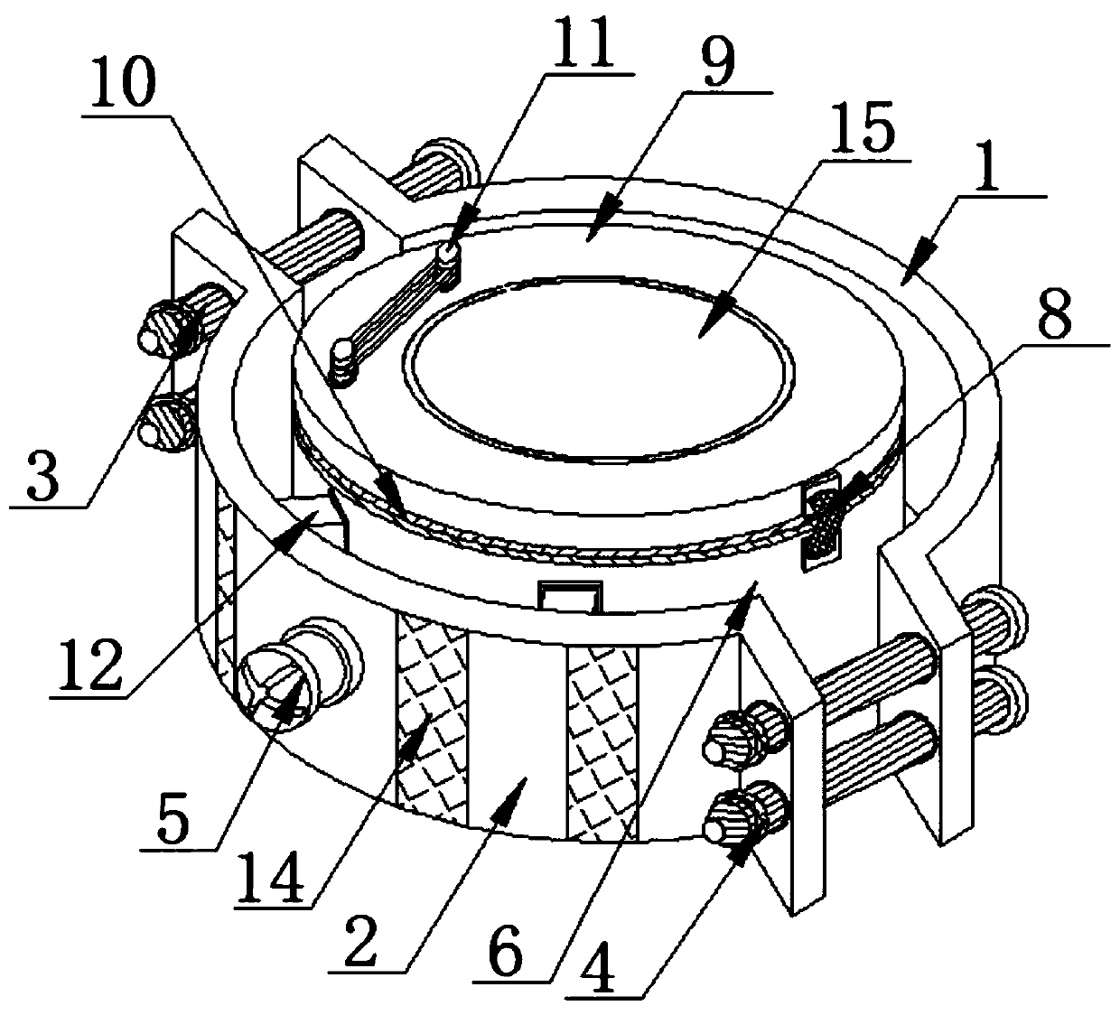
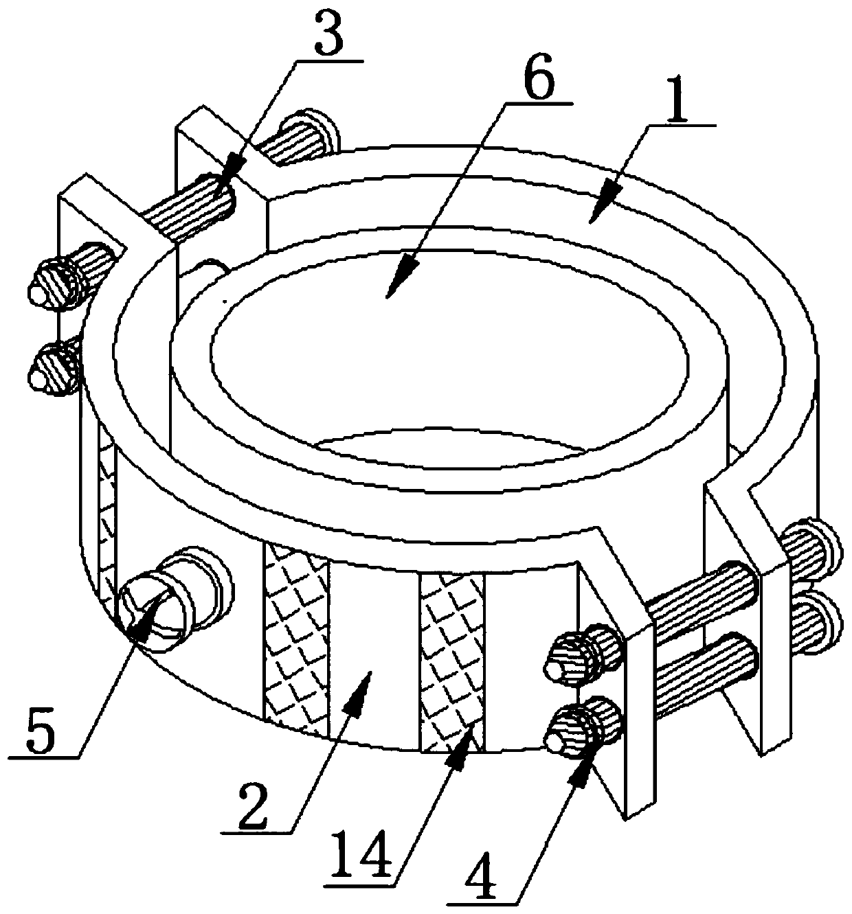
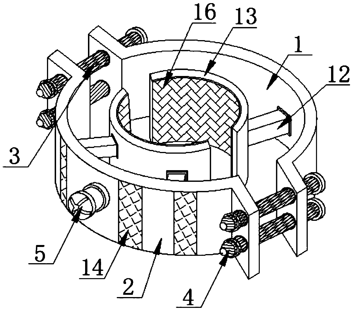
[0025] See Figure 1-5 , The present invention provides a technical solution: a new type of protection device based on road and bridge protection, including a first fixed ring 1 and a second fixed ring 2, the tops on both sides between the first fixed ring 1 and the second fixed ring 2 Both the bottom and the bottom are movably connected by a fixing bolt 3. A fixing nut 4 is threaded on one side of the fixing bolt 3, and the middle of the surface of the first fixing ring 1 and the second fixing ring 2 pass through the limit bolt 5, two limit bolts 5 The ends far away from the first fixing ring 1 and the second fixing ring 2 are threadedly connected with a protective box 6. The surface of the protective box 6 and the connection with the limit bolt 5 is provided with a threaded groove 7 on the surface of the protective box 6 A movable hinge 8 is fixedly connected to the top of the movable hinge 8, a protective cover 9 is fixedly connected to the surface of the movable hinge 8, the bottom of the protective cover 9 and the top of the protective box 6 are fixedly connected with a magnet 10, and the two magnets 10 are in contact with each other, The magnets 10 are attracted to each other to prevent the protective cover 9 from opening, and it is considered that the force is large, and it can be pulled open directly.
[0026] In the present invention, the two sides of the top of the protective cover 9 and the side away from the movable hinge 8 are fixedly connected with fixed posts 11, and a handle is fixedly connected between the two fixed posts 11, and the movable hinge 8 is a movable hinge. To connect the protective cover and the protective box 6.
[0027] In the present invention, a connecting rod 12 is fixedly connected to the middle portions on both sides between the first fixing ring 1 and the second fixing ring 2, and the ends of the two connecting rods 12 away from the first fixing ring 1 and the second fixing ring 2 are both fixed. It penetrates the protective box 6 and extends to the inner cavity of the protective box 6.
[0028] In the present invention, one end of the connecting rod 12 located in the inner cavity of the protective box 6 is fixedly connected with an extruded plate 13, and the side of the extruded plate 13 close to the protective box 6 is in contact with the inner surface of the protective box 6.
[0029] In the present invention, both sides of the surface of the first fixing ring 1 and the second fixing ring 2 and the side away from the protective box 6 are fixedly connected with a reflector 14 which is a mirror-like material for reflecting light.
[0030] In the present invention, a through hole is opened in the middle of the surface of the protective cover 9, and the inner surface of the through hole in the middle of the top of the protective cover 9 is fixedly connected with a glass visual plate 15 which is a tempered glass plate, which can be seen through and used for observation .
[0031] In the present invention, the inner surface of the extrusion plate 13 is fixedly connected with a soft rubber pad 16, and the middle of the bottom of the protective box 6 is provided with an opening. The soft rubber pad 16 prevents the extrusion plate 13 from being excessively stressed and causing internal screw damage.
[0032] In the present invention, the number of reflectors 14 is eight, and each of them is uniform in size and arranged on both sides of the middle of the outer surface of the first fixing ring 1 and the second fixing ring 2.
[0033] When in use, first select the protective equipment suitable for the size of the bridge screw to be protected. First, lift the protective cover 9 by the handle and the fixed post 11, and then the movable hinge 8 will prevent the protective cover 9 from falling , Then screw the fixing bolt 3 to make the first fixing ring 1 and the second fixing ring 2 movable, then pull the first fixing ring 1 and the second fixing ring 2 outward to the limit, and then put the whole device on the screw , The nut on the top of the screw is in the inner cavity of the protective box 6. At this time, the fixing bolt 3 can be reversed to tighten the first fixing ring 1 and the second fixing ring 2, and pushing the pressing plate 13 to the inner screw Squeeze to achieve the effect of fixing, then close the protective cover 9 so that the magnet 10 will attract the protective cover 9. At this time, you can turn the limit bolt 5 to connect the first fixing ring 1 and the second fixing ring 2 is fixed with the protective box 6 so that the protective device is installed. The light source projected by the reflector 14 is reflected at night for display, and the glass visible plate 15 on the top of the protective cover 9 is used to check the internal screw condition.
[0034] It should be noted that in this article, relational terms such as first and second are only used to distinguish one entity or operation from another entity or operation, and do not necessarily require or imply one of these entities or operations. There is any such actual relationship or order between. Moreover, the terms "include", "include" or any other variants thereof are intended to cover non-exclusive inclusion, so that a process, method, article or device including a series of elements not only includes those elements, but also includes those that are not explicitly listed Other elements of, or also include elements inherent to this process, method, article or equipment.
[0035] Although the embodiments of the present invention have been shown and described, those of ordinary skill in the art can understand that various changes, modifications, and substitutions can be made to these embodiments without departing from the principle and spirit of the present invention. And variations, the scope of the present invention is defined by the appended claims and their equivalents.

PUM

no PUM

Description & Claims & Application Information

We can also present the details of the Description, Claims and Application information to help users get a comprehensive understanding of the technical details of the patent, such as background art, summary of invention, brief description of drawings, description of embodiments, and other original content. On the other hand, users can also determine the specific scope of protection of the technology through the list of claims; as well as understand the changes in the life cycle of the technology with the presentation of the patent timeline. Login to view more.

Similar technology patents

Pipeline crawler based on pipeline detection

ActiveCN111911744Asave time at workReduce work steps
Owner:湖北科规检测有限公司

Multifunctional sealing pliers

InactiveCN104440643AReduce work stepsReduce the type and number of tools used
Owner:STATE GRID CORP OF CHINA +2

Spraying device for tomato planting

InactiveCN109006403AReduce work stepsImprove work efficiency
Owner:芜湖神唐生态农业有限公司

Industrial PLC (programmable logic controller) and BIM (building information modeling) combined model watching interactive control system

PendingCN114596392AThe display system is clearReduce work steps
Owner:吉林省基洋建筑工程设计有限公司

Plastic integrated pipe network water quality detection device

PendingCN114720648AReduce work stepsImprove efficiency
Owner:云南傲远智能环保科技有限公司

Classification and recommendation of technical efficacy words

  • Reduce work steps
  • easy to use

Method for manufacturing thermoelectric module having high-insulation thermal coupling surface, low thermal resistance and no brazing layer

ActiveCN101783386AReduce work stepsavoid relative motion
Owner:SHANGHAI SHENHE THERMO MAGNETICS ELECTRONICS CO LTD +1

Welding robot capable of grinding surfaces

InactiveCN107378960Aeasy to useReduce work steps
Owner:WUHU CHAOYUANLI IND DESIGN CO LTD

Corrugated roller with plum-shaped grooves

PendingCN108749157AReduce work stepsReduce workload
Owner:SHANGHAI DASONG CORRUGATING ROLL IND

Parking terminal data processing method and apparatus

InactiveCN104021659AReduce work stepssave time at work
Owner:EASTCOMPEACE TECH

Laser assisted total joint arthroplasty

InactiveUS20090234360A1easy to use
Owner:ALEXANDER VLADIMIR

Enclosure for a portable hemodialysis system

ActiveUS20090114582A1easy to use
Owner:DEKA PROD LLP
Why Eureka
Try Eureka