
Spline shaft hot forging device

A technology for processing devices and spline shafts, applied in forging/pressing/hammer devices, metal processing equipment, manufacturing tools, etc., can solve problems such as errors and forging errors, improve precision, reduce costs, and reduce solid waste The effect of the emissions

Inactive Publication Date: 2015-12-23
WANXIANG QIANCHAO TRANSMISSION SHAFT +1
View PDF6 Cites 7 Cited by
  • Summary
  • Abstract
  • Description
  • Claims
  • Application Information

AI Technical Summary

Problems solved by technology

[0009] 3. Forging error (also known as wrong shift or wrong mold), both the main parting surface and the concave parting surface of the flat forging may have errors, usually between 0.8mm and 1mm

Method used


Image

  • Spline shaft hot forging device
  • Spline shaft hot forging device

Examples


Embodiment Construction

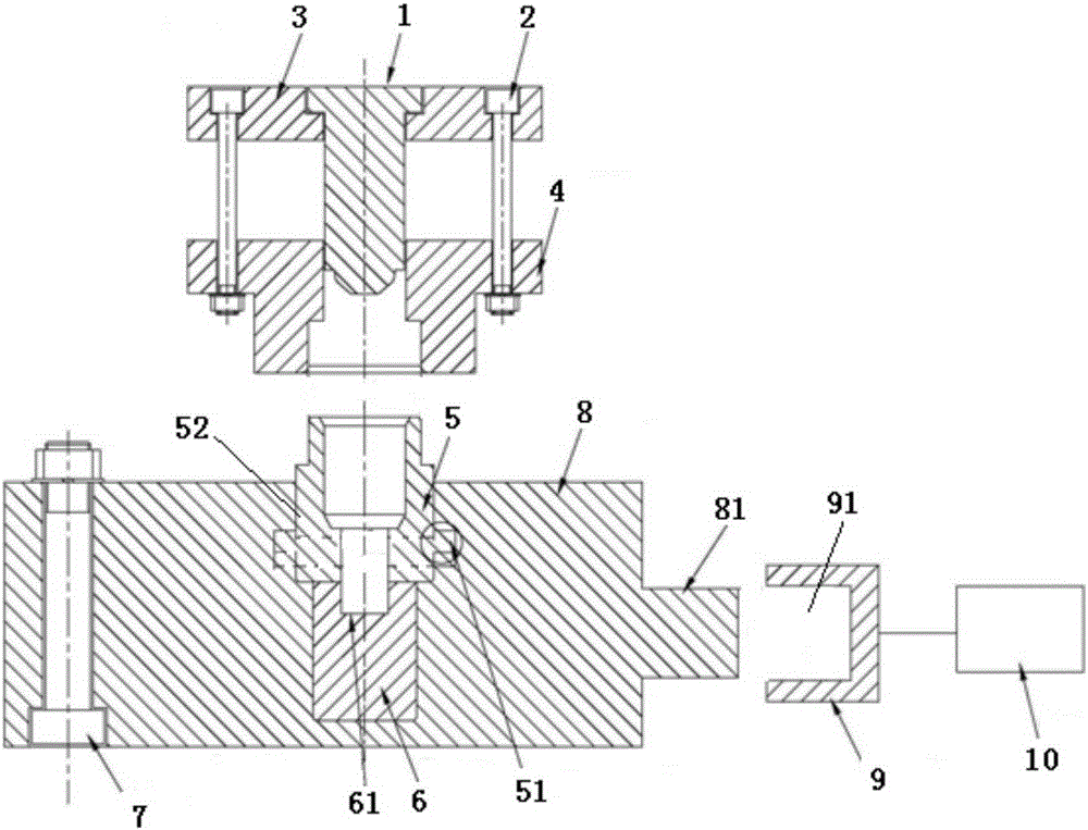
[0023] The present invention will be described in detail below in conjunction with accompanying drawing: figure 2 As shown, the present invention comprises upper mold, lower mold, cylinder locking device, and described upper mold is made up of punch 1, four screw rods 2, positioning plate 3, upper guide sleeve 4, and this upper guide sleeve 4 and positioning plate 3 are connected and fixed by four screw rods 2, and a punch 1 is arranged at the center between the upper guide sleeve 4 and the positioning plate 3, and the positioning plate 3 is connected with the stamping equipment; the lower die is composed of the lower die 5 , the lower die 6, the bolt 7, and the lower die base 8. The lower die 5 and the lower die 6 are installed in the center of the lower die base 8. The lower die 5 is located on the lower die 6. The bolts 7 is located on one side of the lower mold base 8, and the lower die 5 and the upper guide sleeve 4 are clearance locking fits; the cylinder locking device...


PUM


Abstract

The invention relates to a spline shaft hot forging device. The spline shaft hot forging device comprises an upper die, a lower die and a cylinder locking device. The upper die is composed of a punch, four screws, a positioning plate and an upper guide sleeve. The upper guide sleeve and the positioning plate are connected and fixed through the four screws. The punch is arranged at the central position between the upper guide sleeve and the positioning plate. The positioning plate is connected with a punching device. The lower die is composed of a lower female die, a lower material fixing die, a bolt and a lower die holder. The lower female die and the lower material fixing die are arranged at the central position of the lower die holder. The lower female die is located above the lower material fixing die. The bolt is located on one side of the lower die holder. The cylinder locking device is composed of a round sleeve and a reciprocating stroke cylinder. The round sleeve is connected with the movable head end of the reciprocating stroke cylinder. The opening end of the round sleeve is located in the protruding head end of the lower die holder. The spline shaft hot forging device has the beneficial effects that machining procedures can be reduced, the machining cost is low, and the forge piece error range is small.

Description

technical field [0001] The invention belongs to the technical field of hot forging processing devices, in particular to a spline shaft hot forging processing device. Background technique [0002] The general forging processing method is: hot forged spline shaft products are generally forged on a flat forging machine; the flat forging machine has two mutually perpendicular parting surfaces, and the main parting surface is between the punch 12 and the die 11. The other parting surface is between the two divisible halves of the die, and the die forging process is as follows: figure 1 ; [0003] Put the heated bar in the cavity of the fixed die M1, and determine the length L1 of the blank with the front baffle or the rear baffle; figure 1 As shown in -a; the main slider and the clamping slider of the flat forging machine move at the same time, when the die 11 clamps the bar (such as figure 1 -b), the main slider continues to move, the part of the bar length L1 is deformed und...

Claims


Application Information

Patent Timeline
Patent Type & Authority Applications(China)
IPC IPC(8): B21J13/02B21K1/06
CPCB21J13/02B21K1/066
Inventor 戚利明
Owner WANXIANG QIANCHAO TRANSMISSION SHAFT
Learn More