Speed ​​reduction device for rotating parts

A technology of rotating parts and rotating speed, which is applied in the direction of automatic brakes, brake types, mechanical equipment, etc., can solve the problems of high use cost and manufacturing cost, and achieve the effects of low use cost and maintenance cost, strong applicability, and reduced speed

Active Publication Date: 2021-05-04
山东未来城建筑工程有限公司
View PDF4 Cites 0 Cited by
  • Summary
  • Abstract
  • Description
  • Claims
  • Application Information

AI Technical Summary

Problems solved by technology

[0002] At present, in industrial production sites, in order to prevent the rotating parts in the drive device from rotating too fast and irreversible, specific devices are used. However, most of the existing deceleration devices are electronic instruments. are higher

Method used


Image

  • Speed ​​reduction device for rotating parts
  • Speed ​​reduction device for rotating parts
  • Speed ​​reduction device for rotating parts

Examples


Embodiment Construction

[0020] The following will clearly and completely describe the technical solutions in the embodiments of the present invention with reference to the accompanying drawings in the embodiments of the present invention. Obviously, the described embodiments are only some, not all, embodiments of the present invention. Based on the embodiments of the present invention, all other embodiments obtained by persons of ordinary skill in the art without making creative efforts belong to the protection scope of the present invention.

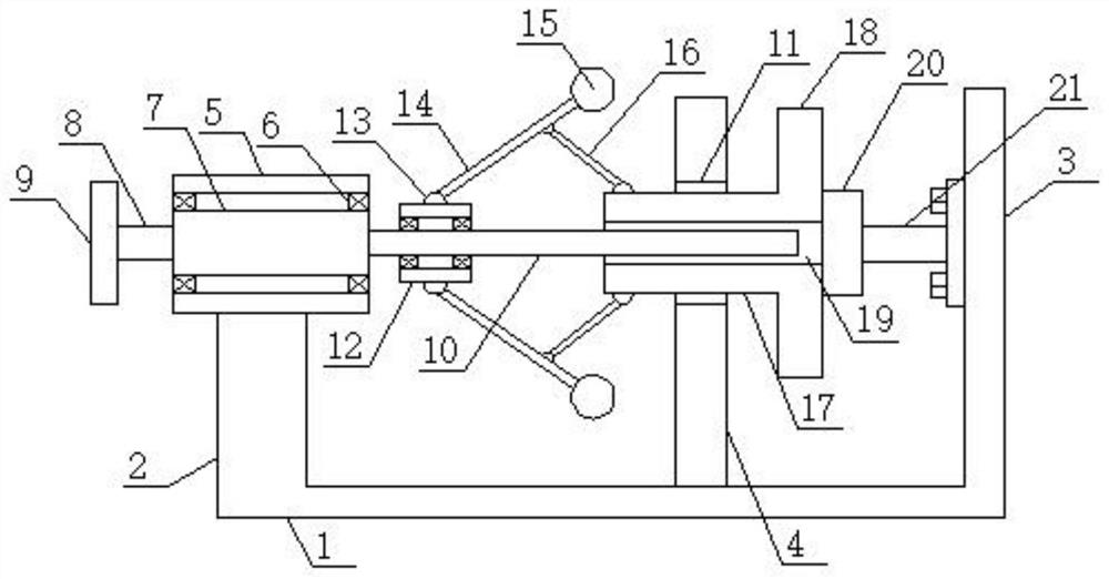
[0021] see figure 1 , an embodiment provided by the present invention: includes a bottom support substrate 1, the two sides of the bottom support substrate 1 are respectively provided with a main support block 2 and a main vertical plate 3 of an integral structure with it, and the bottom support substrate 1 An installed friction riser 4 is installed in the middle, and the middle part of the installed friction riser is provided with a main through hole structur...


PUM


Abstract

The invention discloses a speed reducing device for a rotating component, which comprises a bottom supporting base plate. The present invention utilizes the mechanical principle to realize the effect of reducing the speed, so its manufacturing cost, use cost and maintenance cost are all relatively low. Friction is generated between the parts, which can effectively consume energy and reduce the speed. Moreover, the device has a threaded structure to install a screw-in gravity ball head mechanism, which can be disassembled and screwed in using the threaded structure. Therefore, ball heads of different qualities are used, and the applicability is strong. In addition, the device has a rotating structure threaded connection type static conversion connection mechanism, which can be installed on the end face of the rotating device, and then connected with the stationary part to realize state conversion. In addition, the device It has a coil spring compression type normal rotation speed control mechanism, which utilizes the elasticity of the coil spring.

Description

technical field [0001] The invention relates to the technical field of speed reduction, in particular to a speed reduction device for rotating components. Background technique [0002] At present, in industrial production sites, in order to prevent the rotating parts in the drive device from rotating too fast and irreversible, specific devices are used. However, most of the existing deceleration devices are electronic instruments. are relatively high. Contents of the invention [0003] The object of the present invention is to provide a speed reduction device for rotating components to solve the problems raised in the background art above. [0004] In order to achieve the above object, the present invention provides the following technical solutions: a speed reduction device for rotating parts, including a bottom support base plate, and the two sides of the bottom support base plate are respectively provided with a main support block and a main vertical plate of an integr...

Claims


Application Information

Patent Timeline
Patent Type & Authority Patents(China)
IPC IPC(8): F16D59/02
CPCF16D59/02
Inventor 郭水春
Owner 山东未来城建筑工程有限公司
Why Eureka
Try Eureka