Temperature transmitter fixing device

A technology for temperature transmitters and fixing devices, applied in the direction of supporting machines, mechanical equipment, machine platforms/supports, etc., can solve problems such as shaking, detection deviation, damage, etc., and achieve the effect of avoiding damage

Inactive Publication Date: 2019-12-13
西安西派测控技术有限公司
View PDF3 Cites 1 Cited by
  • Summary
  • Abstract
  • Description
  • Claims
  • Application Information

AI Technical Summary

Problems solved by technology

[0003] Since the existing integrated temperature transmitter is installed on the pipeline, there is no special device for fixing it, so if it moves during use, it is easy to cause it to shake or be damaged, and it will also cause deviations in detection

Method used


Image

  • Temperature transmitter fixing device
  • Temperature transmitter fixing device
  • Temperature transmitter fixing device

Examples


Embodiment 1

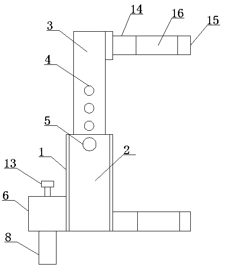
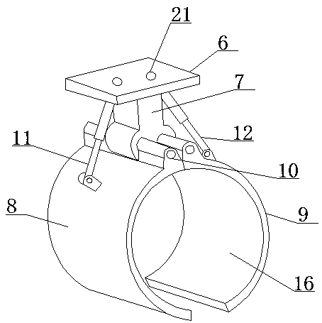
[0024] like Figure 1-3 As shown, the fixing device of the integrated temperature transmitter according to the embodiment of the present invention includes a cylinder body 1 and a limit sleeve 2 located at the inner bottom end of the cylinder body 1, and the limit sleeve 2 is provided with an extension To the column 3 at the top of the cylinder 1, one side of the column 3 is provided with a number of evenly distributed limiting grooves 4, and one side of the cylinder 1 is provided with tight fittings extending into the limiting groove 4. Fasten the bolt 5, the bottom end of one side of the cylinder 1 is provided with a side plate 6, the bottom end of the side plate 6 is provided with a connecting block 7, and the bottom end of the connecting block 7 is symmetrically provided with a fixed piece 8 and The second fixed piece 9, the first fixed piece 8 and the second fixed piece 9 are respectively connected to the connecting block 7 through the rotating shaft 10, the side of the f...

Embodiment 2

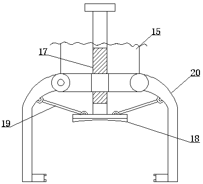
[0026] like Figure 1-3 As shown, the clamping mechanism 15 includes a hole 16 located on the horizontal plate 14, the hole 16 is provided with a threaded rod 17 passing through the horizontal plate 14, and the other threaded rod 17 is The side is provided with push plate 18, and the top two sides of described push plate 18 are symmetrically provided with the connecting rod 19 that obliquely arranges, and the other side of described connecting rod 19 is provided with clamping rod 20, and the top of described clamping rod 20 Both are connected to the horizontal plate 14, the clamping rod 20 is an arc structure, and the clamping rod 20 is connected to the horizontal plate 14 through a roller.

Embodiment 3

[0028] like Figure 1-3 As shown, the bottom end of the push plate 18 is provided with an arc-shaped groove, and a rubber cushion is provided in the arc-shaped groove, and the side plate 6 and the connecting block 7 are provided with a 11 and the threaded groove 21 that matches the threaded rod two 12, the side of the fixed piece one 8 and the fixed piece two 9 that are close to each other are provided with a matching flexible layer, located at the top of one side of the column 3 The said transverse plate 14 is connected with it by a backing plate. It is not difficult to see from the above design that the design of the rubber cushion can better protect the outer wall of the device from being scratched.

[0029] In order to facilitate the understanding of the above-mentioned technical solution of the present invention, the working principle or operation mode of the present invention in the actual process will be described in detail below.

[0030] In actual application, the s...


PUM


Abstract

The invention discloses a temperature transmitter fixing device. The device comprises a cylinder body and a limiting sleeve, wherein the limiting sleeve is located at the bottom end in the cylinder body, and a stand column extending to the top end of the cylinder body is arranged in the limiting sleeve; a plurality of uniformly distributed limiting grooves are formed in one side of the stand column, wherein fastening bolts extending into the limiting grooves are arranged on one side of the cylinder body; a side plate is arranged at the bottom end of one side of the cylinder body, wherein a connecting block is arranged at the bottom end of the side plate; and a fixing sheet I and a fixing sheet II are symmetrically arranged at the bottom end of the connecting block, wherein the fixing sheetI and the fixing sheet II are connected with the connecting block through rotating shafts correspondingly. The temperature transmitter fixing device has the beneficial effects that the device is adapted to pipelines with different diameters, so that the purpose of fixing the pipelines is achieved, the situation of deviation of detection data caused by shaking under accidental conditions or movement of an integrated temperature transmitter is avoided, and damage to the integrated temperature transmitter in use is also avoided.

Description

technical field [0001] The invention relates to the technical field of temperature transmitters, in particular to a temperature transmitter fixing device. Background technique [0002] The integrated temperature transmitter is a combination of a temperature sensor and a transmitter, which converts the temperature signal within the range of -200 to +1600°C into a two-wire electrical signal and transmits it in a very simple way. The integrated temperature transmitter is an essential temperature instrument in the production line. [0003] Since the existing integrated temperature transmitter is installed on the pipeline, there is no special device for fixing it, so if it is moved during use, it is easy to cause it to shake or be damaged, and it will also cause deviations in detection. [0004] Aiming at the problems in the related technologies, no effective solution has been proposed yet. Contents of the invention [0005] Aiming at the problems in the related art, the pres...

Claims


Application Information

Patent Timeline
Patent Type & Authority Applications(China)
IPC IPC(8): F16M13/02F16M11/04
CPCF16M11/04F16M13/02
Inventor 李传鑫
Owner 西安西派测控技术有限公司
Why Eureka
Try Eureka