Linkage type switching power source aging clamp

A switching power supply and linkage technology, applied in power supply testing, measuring electrical variables, components of electrical measuring instruments, etc., can solve the problems of low efficiency, inconvenient aging operation of double-terminal wiring switching power supply, etc., to achieve convenient operation and meet aging requirements. Demand and achieve the effect of linkage operation

Active Publication Date: 2019-12-13
湖南华鑫电子科技有限公司
View PDF7 Cites 1 Cited by
  • Summary
  • Abstract
  • Description
  • Claims
  • Application Information

AI Technical Summary

Problems solved by technology

[0003] Aiming at the deficiencies in the prior art, the purpose of the present invention is to provide a linkage type switching power supply aging fixture to solve the problems of inconvenient operation and low efficiency of double-terminal wiring switching power supply aging

Method used


Image

  • Linkage type switching power source aging clamp
  • Linkage type switching power source aging clamp
  • Linkage type switching power source aging clamp

Examples


Embodiment

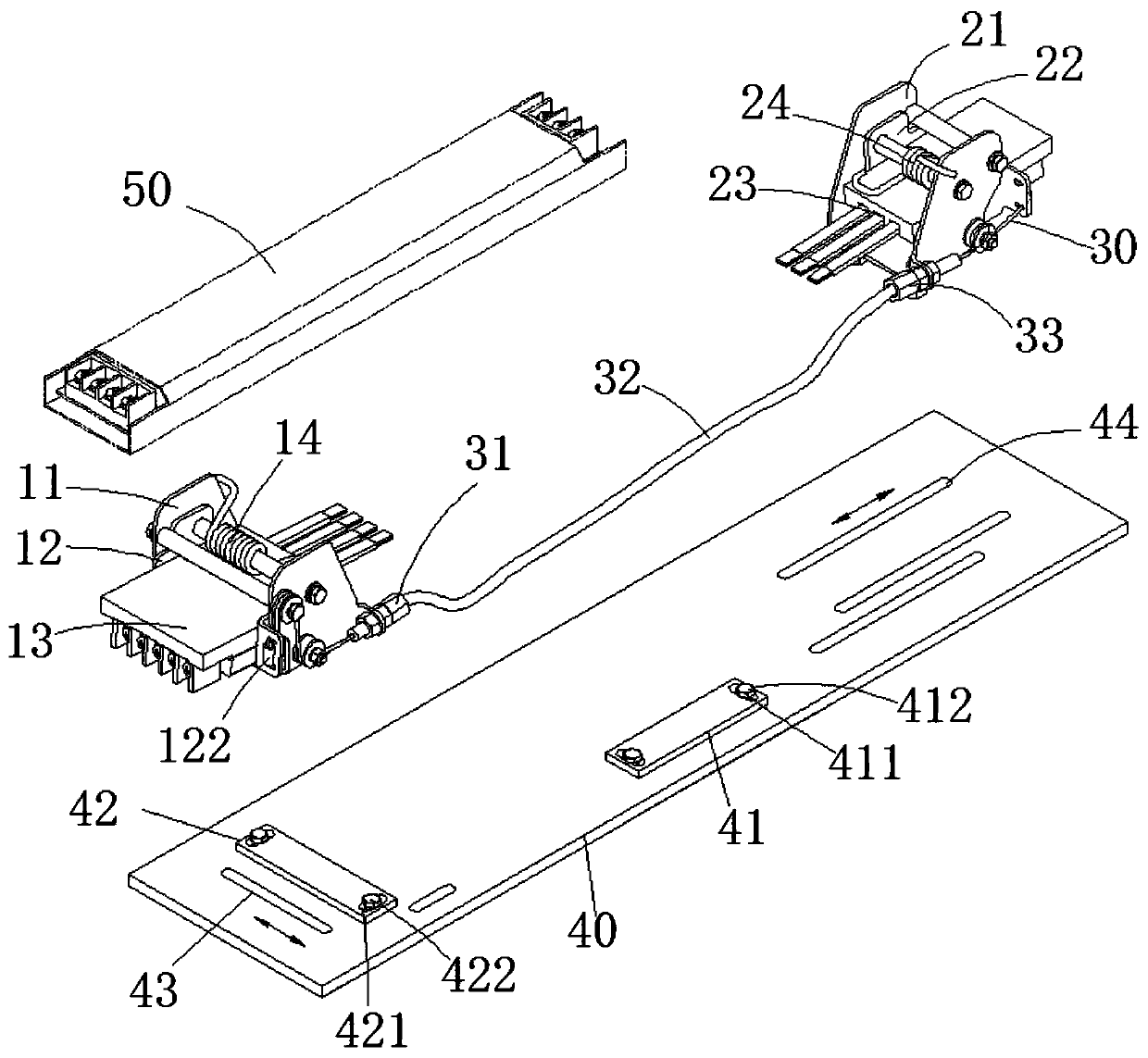
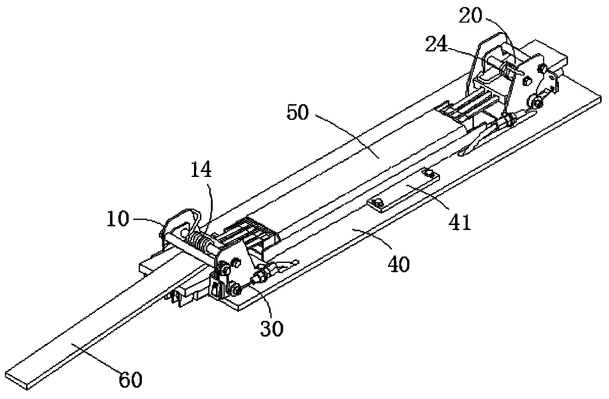
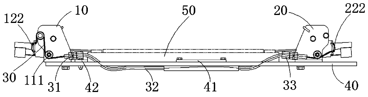
[0053] Example: Reference Figure 1 to Figure 13 , the present invention provides a linkage type switching power supply aging fixture, comprising: a bottom plate 40, a driving end 10 located on one side of the bottom plate 40, a driven end 20 arranged on the other side of the bottom plate 40 opposite to the driving end 10, and a linkage rope 30, wherein The bottom plate 40 is used to place the switching power supply 50, the switching power supply 50 double-terminal wiring switching power supply; the active end 10 includes the first fixed support plate 11, the first rotating support plate 12, the first wiring assembly 13 and the first torsion spring 14 ; the first fixed support plate 11 is fixed on the bottom plate 40, the first rotating support plate 12 is rotatably connected to the first fixed support plate 11, and the first wiring assembly 13 is fixedly connected to the first rotating support plate 12; the first twist The spring 14 is fixed on the first rotating support plat...


PUM


Abstract

The invention discloses a linkage type switching power source aging clamp. The linkage type switching power source aging clamp comprises a bottom plate, a driving end, a driven end, and a linkage rope; the bottom plate is used for placing a double-end-wired switching power source; the driving end is located on one side of the bottom plate and comprises a first fixed supporting plate, a first rotary supporting plate, a first wiring assembly and a first torsional spring, wherein the first torsional spring applies downward pressure to the first wiring assembly; the driven end is opposite to the driving end and is arranged on the other side of the bottom plate; the driven end comprises a second fixed supporting plate, a second rotary supporting plate, a second wiring assembly and a second torsional spring, wherein the second torsional spring applies downward pressure to the second wiring assembly; and one end of the linkage rope is connected with the first rotary supporting plate of the driving end, and the other end of the linkage rope is connected with the second rotary supporting plate of the driven end, and therefore, the second rotary supporting plate can be driven to rotate through the rotation of the first rotary supporting plate; the linkage rope is fixed to the bottom plate; and at least part of the linkage rope penetrates through the bottom plate from below. According tothe linkage type switching power source aging clamp of the invention, the aging of two ends of the switching power source is realized; and operation just needs to be performed at the driving end and the driven end, and therefore, the switching-on and switching-off of the switching power source are synchronously realized.

Description

technical field [0001] The invention relates to the field of switching power supply aging, more specifically, it relates to a linkage type switching power supply aging fixture, which is mainly used for aging of switching power supply with double-terminal connection. Background technique [0002] Power supply aging is a necessary link in the production process of switching power supply products. When aging, the switching power supply needs to be connected to the load, and then output continuously for a period of time. Usually, it is connected to the switching power supply through the terminal block, which requires the power switch to be fixed and wired. For the double-terminal switching power supply, the existing power aging device can only be connected to the load at one end of the switching power supply. For the double-terminal switching power supply, it is not conducive to the completion of the aging work. Even if an existing power aging device is installed at both ends, ...

Claims


Application Information

Patent Timeline
Patent Type & Authority Applications(China)
IPC IPC(8): G01R31/40G01R1/04
CPCG01R31/40G01R1/0408
Inventor 荣成杰唐卫华
Owner 湖南华鑫电子科技有限公司
Why Eureka
Try Eureka