Storage battery fixing frame

A fixing frame and battery technology, which is applied to battery pack components, circuits, electrical components, etc., can solve the problems of battery loosening, displacement power failure, and the circuit cannot achieve a safe explosion-proof type, and achieves reliable and simple fixed structure. , the effect of easy installation

Inactive Publication Date: 2019-12-13
哈尔滨东方报警科技有限公司
View PDF0 Cites 0 Cited by
  • Summary
  • Abstract
  • Description
  • Claims
  • Application Information

AI Technical Summary

Problems solved by technology

[0002] At present, in the field of explosive gas environment, the application of portable explosion-proof electrical equipment is becoming more and more extensive. Due to the continuous increase of the functions of portable explosion-proof equipment, the types of power supply batteries have also become diversified. When the battery capacity and volume are large, the circuit can no longer achiev

Method used


Image

  • Storage battery fixing frame
  • Storage battery fixing frame

Examples


Embodiment 1

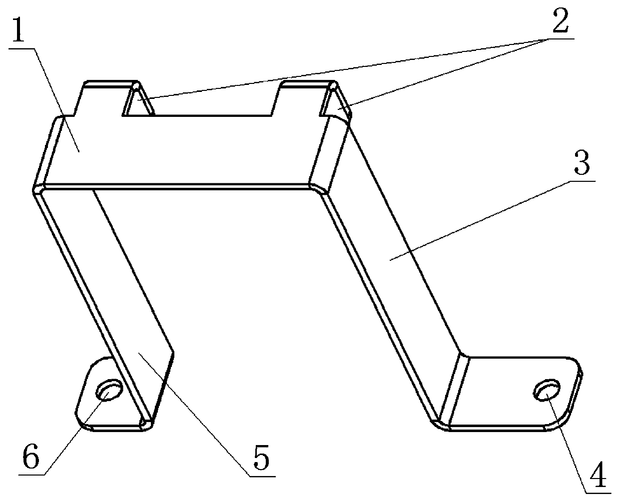
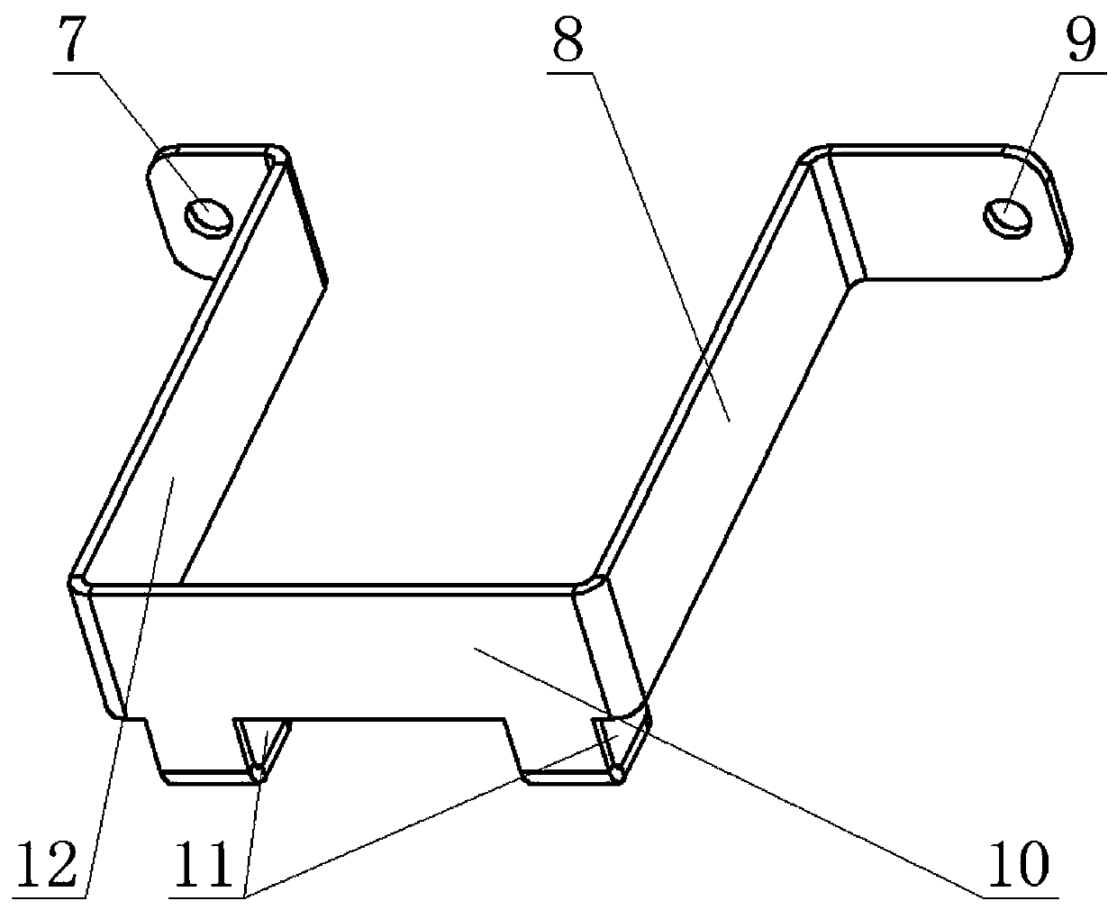
[0013] A battery fixing frame, comprising an upper frame beam 1 and a lower frame beam 10; it is characterized in that: the upper frame beam 1 and the lower frame beam 10 have a U-shaped structure; the upper frame beam 1 includes a bottom plate of the upper frame beam 1 and a left side plate 5 of the upper frame The upper shelf right side plate 3; the lower shelf beam 10 includes the lower shelf beam 10 bottom plate, the lower shelf left side plate 12, and the lower shelf right side plate 8; the upper shelf limit hook 2 is provided on the side of the upper shelf beam 1 bottom plate, and the lower shelf The bottom plate of the beam 10 is provided with a lower shelf limit hook 11; the top of the left side plate 5 of the upper shelf and the right side plate 3 of the upper shelf are all provided with an upper shelf fixing plate; and the mounting hole 4 on the right side of the upper frame; the top of the left side plate 12 of the lower frame and the right side plate 8 of the lower ...

Embodiment 2

[0015] The technical solution adopted in the present invention is: the positioning storage battery fixing frame is divided into an upper shelf and a lower shelf. The upper frame adopts a U-shaped frame structure, and two limit hooks are designed on the upper part of the U-shaped frame; the lower frame also adopts a U-shaped frame structure, and two limit hooks are designed on the lower part of the U-shaped frame. The battery is placed between the upper shelf and the lower shelf, the U-shaped shelf structure is positioned left and right and up and down, and the upper and lower sets of limit hooks are positioned front and back.


PUM


Abstract

The invention discloses a storage battery fixing frame. The fixing frame comprises an upper frame beam and a lower frame beam. The upper frame beam and the lower frame beam are in a U-shaped structure. The upper frame beam comprises an upper frame beam bottom plate, an upper frame left side plate and an upper frame right side plate. A lower frame beam comprises a lower frame beam bottom plate, a lower frame left side plate and a lower frame right side plate. An upper frame limiting hook is arranged on a side surface of the upper frame beam bottom plate, and a lower frame limiting hook is arranged on the lower frame beam bottom plate. Upper frame fixing plates are arranged at top ends of the upper frame left side plate and the upper frame right side plate. An upper frame left side installation hole and an upper frame right side installation hole are arranged in the upper frame fixing plate. Lower frame fixing plates are arranged at the top ends of the lower frame left side plate and thelower frame right side plate. A lower frame left side installation hole and a lower frame right side installation hole are arranged below the lower frame fixing plate. The fixing frame has advantagesthat storage battery positioning and assembling can be achieved; a fixing structure is reliable, and the structure is simple; and installation is convenient.

Description

technical field [0001] The invention relates to a battery fixing frame, in particular to a battery fixing frame for positioning inside an explosion-proof box. Background technique [0002] At present, in the field of explosive gas environment, the application of portable explosion-proof electrical equipment is becoming more and more extensive. Due to the continuous increase of the functions of portable explosion-proof equipment, the types of power supply batteries have also become diversified. When the battery capacity and volume are large, the circuit can no longer achieve intrinsic safety. type explosion-proof type, so the battery needs to be placed inside the explosion-proof explosion-proof box. In the past, the method of fixing the battery was a single mounting bracket and the bottom glue, which was relatively firm. However, when the equipment vibrates strongly during transportation and use, the battery There is a risk of loosening and displacement of power. Contents o...

Claims


Application Information

Patent Timeline
IPC IPC(8): H01M2/10
CPCH01M50/20Y02E60/10
Inventor 姜崇波王锡铜尹莉莉单继平
Owner 哈尔滨东方报警科技有限公司
Why Eureka
Try Eureka