Waste ink conveying device and image forming device

A conveying device, waste ink technology, applied in the direction of inking device, printing device, printing, etc., can solve the problems of leakage, pollution around, faulty waste ink, etc.

Active Publication Date: 2021-06-01
KYOCERA DOCUMENT SOLUTIONS INC
View PDF10 Cites 0 Cited by
  • Summary
  • Abstract
  • Description
  • Claims
  • Application Information

AI Technical Summary

Problems solved by technology

However, in such a structure, there is a concern that the end cap may be broken due to repeated use of the waste ink tank
If the end cap is damaged and cannot be closed, when the waste ink tank is taken out, the waste ink will leak and pollute the surroundings
Or, sometimes the waste ink tank cannot be installed in the normal position if the end cap is damaged and cannot be opened
Or, even in the case where the waste ink tank can be installed in the normal position, there is a concern that the discharge of the waste ink to the waste ink tank will be blocked by the end cap in the closed state, thereby malfunctioning or waste due to clogging of the waste ink. ink leak

Method used


Image

  • Waste ink conveying device and image forming device
  • Waste ink conveying device and image forming device
  • Waste ink conveying device and image forming device

Examples


Embodiment Construction

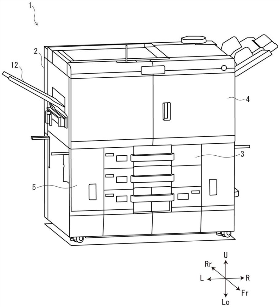
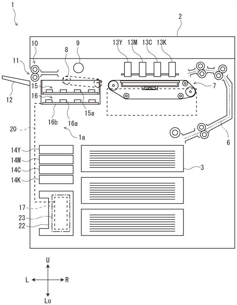
[0046]First,figure 1 withfigure 2 The overall configuration of the printer 1 of the inkjet image forming apparatus according to the first embodiment of the present invention will be described. Below, in order to facilitate explanation,figure 1 The paper surface is close to the front side of the printer 1. The arrows FR, RR, L, R, U, LO, which are suitable in each diagram, indicate the front side of the printer 1, the rear side, the left, the right side, the upper and lower side, respectively.

[0047]Such asfigure 1 withfigure 2 As shown, the printer 1 has a printer main body 2 of a box type shape. At the lower part of the printer body 2, the paper feed cassette 3 containing the storage paper can be contained.

[0048]At the front surface of the printer main body 2, the upper cover 4 and the lower left side cover 5 are provided in a manner that can be opened. By opening the upper side cover 4, the paper conveying unit 7, the end cap unit 15, and the wiping unit 16 are maintained. In addit...


PUM


Abstract

The invention provides a waste ink conveying device and an image forming device. The waste ink conveying device has a waste ink tank which is accommodated in the tank storage part for storing the waste ink, and a tank cover which opens and closes the tank storage part. The waste ink tank has an inflow port through which waste ink flows in from the side of the tank cover. The tank cover has: an inflow nozzle that enters the inflow port to allow waste ink to flow into the waste ink tank; an inflow nozzle operation part that switches the protrusion and retraction of the inflow nozzle so that the inflow nozzle enters and exits relative to the inflow port; and a cover The locking part switches between locking and unlocking of the can cover in a closed state. When the cover lock part is in the locked state and the inflow nozzle is in the retracted state, the cover lock part can be switched to the unlocked state. On the other hand, when the cover lock part is in the locked state and the inflow nozzle is in the protruding state, the cover lock part cannot be switched to the unlocked state. According to the present invention, it is possible to suppress waste ink contamination or failure due to replacement of the waste ink tank.

Description

Technical field[0001]The present invention relates to a waste ink delivery device for transporting waste ink and an image forming apparatus having the waste ink water delivery device.Background technique[0002]In the prior art, the ink jet image forming apparatus is imaged by a recording medium such as a sheet to form an image. In the image forming apparatus, the waste ink generated by the recording head is recovered to the waste ink tray, and is delivered to the waste ink jug and housed in the waste ink tank.[0003]For example, in the waste ink treatment apparatus of the inkjet printer, in the case where the waste ink bottle (waste ink tank) is pushed into the waste ink cartridge from the rear portion side, the rear of the waste ink bottle is formed as before The portion is raised to top. Further, the end cap of the upper portion provided in the rear portion of the waste ink bottle is switched from the closed state to the open state, and the waste ink discharged from the ink discharg...

Claims


Application Information

Patent Timeline
Patent Type & Authority Patents(China)
IPC IPC(8): B41J2/185B41J2/01
CPCB41J2/01B41J2/185B41J2002/1856B41J2/1752B41J2/17553B41J2/18B41J2/1721B41J29/38B41J29/58B41J2002/1728B41J2202/15
Inventor 上野大二郎村岛正树
Owner KYOCERA DOCUMENT SOLUTIONS INC
Why Eureka
Try Eureka