
Rotor tilting device for four-axis unmanned aerial vehicle

A four-axis unmanned aerial vehicle and rotor tilting technology, applied in the field of unmanned aerial vehicles, can solve the problems of low cruising speed, poor maneuverability, and short battery life, and achieve the effects of fast flight speed, simple composition structure, and simple parts processing

Inactive Publication Date: 2019-12-17
PLA PEOPLES LIBERATION ARMY OF CHINA STRATEGIC SUPPORT FORCE AEROSPACE ENG UNIV
View PDF14 Cites 2 Cited by
  • Summary
  • Abstract
  • Description
  • Claims
  • Application Information

AI Technical Summary

Problems solved by technology

[0005] The purpose of the present invention is to solve the above-mentioned problems and provide a rotor tilting device based on a small quadrotor UAV, so as to improve the shortcomings of traditional small quadrotor UAVs such as poor maneuverability, low cruising speed, and short battery life. Expand the application scenarios of traditional small quadrotor drones in the military and civilian fields

Method used


Image

  • Rotor tilting device for four-axis unmanned aerial vehicle
  • Rotor tilting device for four-axis unmanned aerial vehicle
  • Rotor tilting device for four-axis unmanned aerial vehicle

Examples


Embodiment Construction

[0028] In order to make the object, technical solution and advantages of the present invention clearer, the present invention will be further described in detail below in conjunction with the accompanying drawings and embodiments. It should be understood that the specific embodiments described here are only used to explain the present invention, not to limit the present invention.

[0029] In the embodiments of the present disclosure, unless otherwise stated, the orientation words used such as "up", "down" or "top", "bottom" refer to the upper and lower positions of the UAV when it is in level flight. Or top and bottom, "left and right sides" or "both sides" refer to the left and right sides with the rotor connecting rod as the central axis.

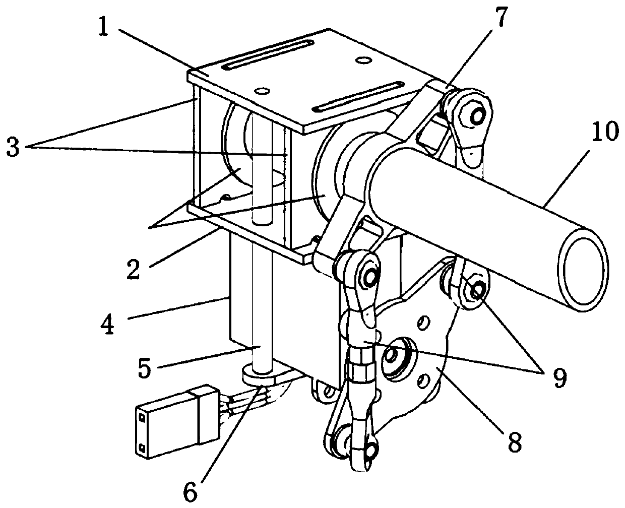
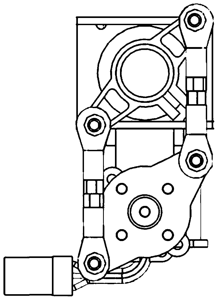
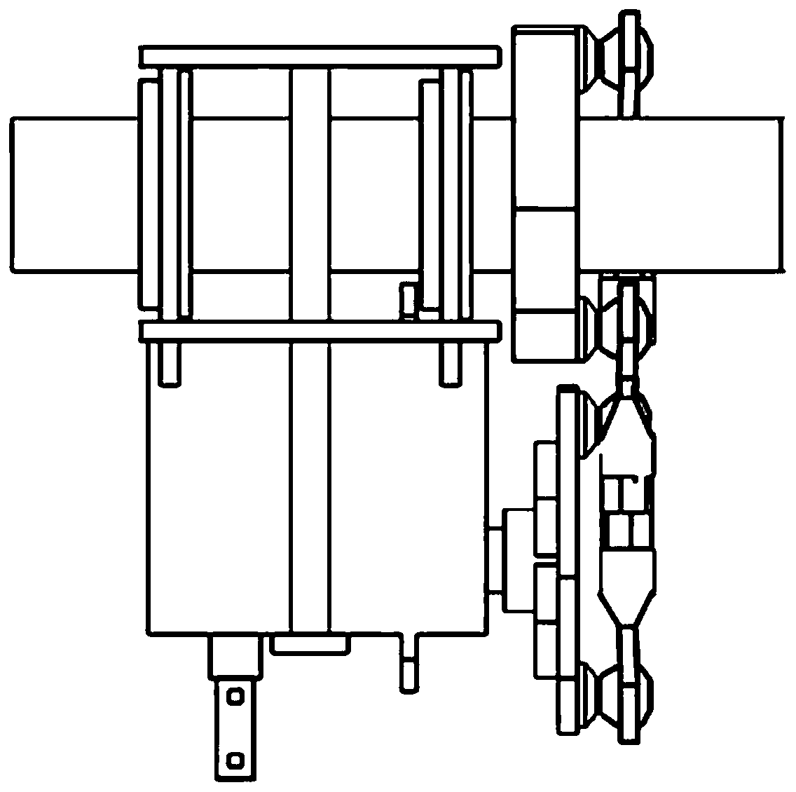
[0030] refer to Figure 1 ~ Figure 3 , a rotor tilting device for a four-axis unmanned aerial vehicle, comprising a steering gear device, a connecting rod device, a bearing and a frame connection part.

[0031] The steering gear device...


PUM


Abstract

The invention relates to a rotor tilting device for a four-axis unmanned aerial vehicle. The rotor tilting device for the four-axis unmanned aerial vehicle comprises a steering engine device, a connecting rod device, a bearing and a frame connecting part; the steering engine device comprises a steering engine, a steering engine bracket and two locating rods, wherein the steering engine is clampedbetween the steering engine bracket and the frame connecting part; the two locating rods are correspondingly and vertically fixed on the two sides of the steering engine; the connecting rod device comprises an upper rocking bar, a lower rocking bar, a rotor connecting rod and two guide rods, wherein the lower rocking bar is connected with a steering engine steering disc; the two ends of the upperrocking bar and the lower rocking bar are correspondingly connected with each other through the guide rods; fixing grooves are correspondingly formed in the centers of the upper rocking bar and the lower rocking bar; the fixing groove of the upper rocking bar is in interference fit with the rotor connecting rod; and the rotor connecting rod penetrates through the frame connecting part and is fixedthrough a bearing. The rotor tilting device for the four-axis unmanned aerial vehicle has the advantages that greater forward flying thrust and rotating torque can be provided for the four-axis unmanned aerial vehicle, the cruising speed and maneuverability can be enhanced, tilting fine adjusting can be continuously generated, and the flight stability can be enhanced.

Description

technical field [0001] The invention relates to a rotor tilting device for a four-axis unmanned aerial vehicle, belonging to the technical field of unmanned aerial vehicles. Background technique [0002] Traditional quadrotor UAVs have always been the mainstream of small UAVs. Because of their advantages of symmetrical aerodynamic layout, strong wind resistance, large load, and easy control, they are currently widely used in many fields. But at the same time, due to its inherent structural reasons, the quadrotor UAV has poor maneuverability and insufficient endurance, which further limits its large-scale promotion and use in the military and civilian fields. At present, the existing solutions to the above problems mainly focus on two aspects, one is to increase the battery capacity within a limited range; the other is to optimize and adjust the flight control system, but the actual effect improvement is not obvious enough. Therefore, people began to explore new means to sol...

Claims


Application Information

Patent Timeline
Patent Type & Authority Applications(China)
IPC IPC(8): B64C9/00B64C27/08B64C27/52
CPCB64C9/00B64C27/08B64C27/52B64U10/10
Inventor 王皓田车学科林郁郑霄何俊伟张国辉
Owner PLA PEOPLES LIBERATION ARMY OF CHINA STRATEGIC SUPPORT FORCE AEROSPACE ENG UNIV
Learn More