Buffer structure of spring bolt of lock
A buffer structure and lock body technology, which is applied in building locks, building construction, construction, etc., can solve problems such as component damage, affecting service life, and noise pollution
- Summary
- Abstract
- Description
- Claims
- Application Information
AI Technical Summary
Problems solved by technology
Method used
Image

Examples
Embodiment Construction
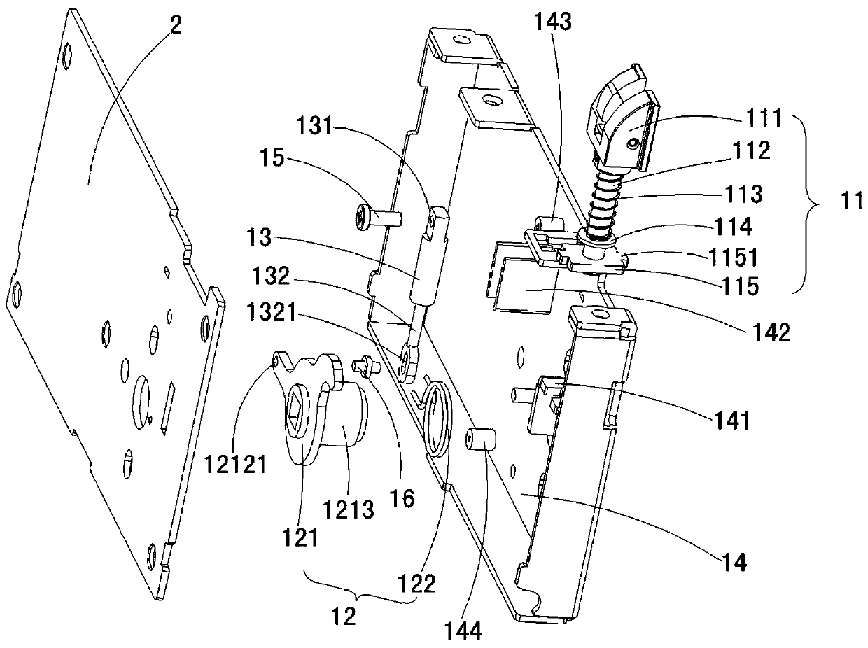
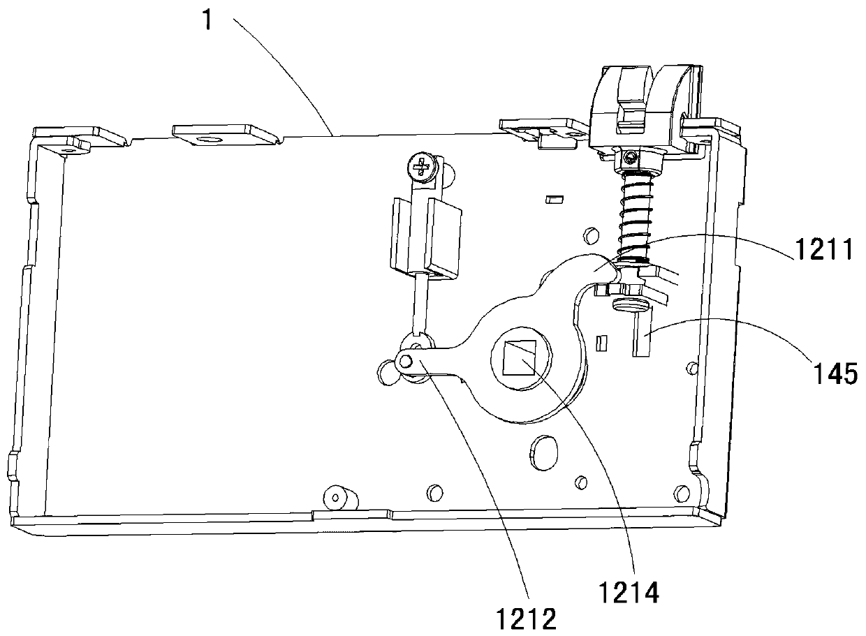
[0015] A lock body bolt buffer structure, including a box bottom assembly 1 and a lock body upper cover 2, characterized in that: the box bottom assembly 1 includes a bolt assembly 11, a bolt bolt assembly 12, a damper 13 and a box body 14. The latch bolt assembly 11 includes a latch bolt 111, a latch bolt pull rod 112, a latch bolt spring 113, a washer 114 and a shifting block 115, and two ends of the shifting block 115 are provided with sliders 1151; 12 includes the oblique tongue dial 121 and the oblique tongue dial reset spring 122. The upper part of the oblique tongue dial is provided with an upper swing arm 1211, the middle part is provided with a oblique tongue dial fixing hole 1214, and the lower part is provided with a lower swing arm 1212. The lower swing arm 1212 is provided with a bolt hole 12121; the left side of the damper 13 is provided with a damper fixing hole 131, the right side is provided with a piston rod 132, and the right side of the piston rod 132 is pro...
PUM
 Abstract
Description
Claims
Application Information
PatSnap Eureka turns technology decisions into work you can execute. Powered by our Innovation Knowledge Graph, it runs expert workflows across engineering, life sciences, materials and intellectual property. Get your review-ready output in minutes.


