Spinal flexion and extension motion damper

a technology of lumbar spinal fusion and damper, which is applied in the field of spinal flexion and extension dampers, can solve the problems of affecting the ability of the spinal cord to properly function, severe pain, and increased risk of adjacent segment disease in patients with lumbar spinal fusion

Active Publication Date: 2009-06-11
CUSTOM SPINE INC
View PDF7 Cites 128 Cited by
  • Summary
  • Abstract
  • Description
  • Claims
  • Application Information

AI Technical Summary

Benefits of technology

[0012]Another aspect provides a method of controlling a degree of motion of a mobile vertebral segment, and includes fixing an anchor of a damper system to a spinous process, coupling a first spring to a portion of the anchor, inserting the first spring and the portion of the anchor into a cylindrical cap, inserting a bar of a cross-connector assembly through the cylindrical cap, connecting the cross-connector assembly to a pair of opposed polyaxial pedicle screw assemblies connected to oppositely positioned pedicles, biasing the first spring to control a motion of the spinous process and the oppositely positioned pedicles, inserting a second spring into the cylindrical cap and adjacent to the portion of the anchor in the cylindrical cap, and inserting a fixation component into the cylindrical cap to set the bar of the cross-connector assembly to the cylindrical cap.
[0013]The damper system includes the anchor, the first spring, and the cylindrical cap. The first spring includes an inner hollow area which is adapted to attach to the anchor. The cylindrical cap is adapted to accommodate the first spring and the portion of the anchor. The cross-connector assembly may be adapted to maintain and secure the posture of a vertebral column. The pair of opposed polyaxial pedicle screw assemblies may be adapted to connect two adjacent vertebrae by spinal fusion. The first spring may be adapted to control a degree of flexion of a vertebral segment. The anchor may include a slot configured to accommodate the spinous process.

Problems solved by technology

Patients who have a lumbar spinal fusion have an increased risk of having adjacent segment disease.
This disease can produce severe pain that can affect the spinal cord's ability to properly function.
It is observed that more rigid spinal fixation systems may increase the risk of complications such as mechanical failure, adjacent segment disease, and device-related osteoporosis.
It provides dynamic stabilization to the motion segment, but typically requires extensive muscle dissection to place, and generally cannot work as an adjacent segment protector above a pedicle screw instrumented fusion.
In this way it is designed to relieve the symptoms of spinal stenosis but typically cannot work when a laminectomy has been performed.
Furthermore, it generally has no ability to limit flexion, and is very rigid.
Moreover, it typically cannot work to protect against adjacent segment disease.
Also, these generally lack a limitation of the damping ability, which may lead to damage of the vertebrae during natural motion.

Method used


Image

  • Spinal flexion and extension motion damper
  • Spinal flexion and extension motion damper
  • Spinal flexion and extension motion damper

Examples


first embodiment

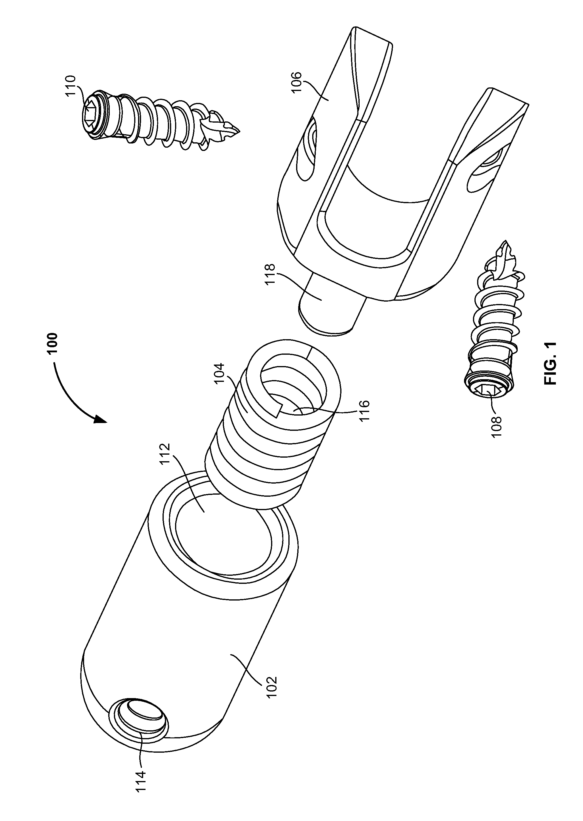
[0030]FIG. 5A illustrates a sectional view of the damper system 100 of FIG. 4 herein. The cylindrical cap 102 further includes a cross-opening 502 which is positioned at an end of the cylindrical cap 102 opposite to the exposed opening of the cylindrical cap 102. The cross-opening 502 cuts the hole 114 horizontally. The hole 114 extends through the thickness of the cylindrical cap 102 and may be threaded at its inner side. Preferably, the spring hitch 118 does not cover the full length of the inner hollow area 116 of the first spring 104. Similarly the first spring 104 preferably does not cover the full length of the inner cavity 112 of the cylindrical cap 102. The first spring 104 may cover the full length of the inner cavity 112 when it becomes compressed.

second embodiment

[0031]FIG. 5B illustrates a sectional view of the damper system 100 of FIG. 4 according to a In this view, a second spring 504 is configured in the inner cavity 112 of the cylindrical cap 102 behind the spring hitch 118. Additionally, the spring hitch 118 in this embodiment comprises a flared end with an annual collar 506 at the tip of the spring hitch 118. The collar 506 provides for a biasing surface for both springs 104, 504.

[0032]The damper system 100 acts as a shock absorber (e.g., any mechanical device designed to smooth out or damp a sudden shock impulse). During the movement of the vertebrae when the vertebral segment receives some sudden forces, the first spring 104 may control a degree of flexion of a vertebral segment and damper the dynamic flexion and extension forces.

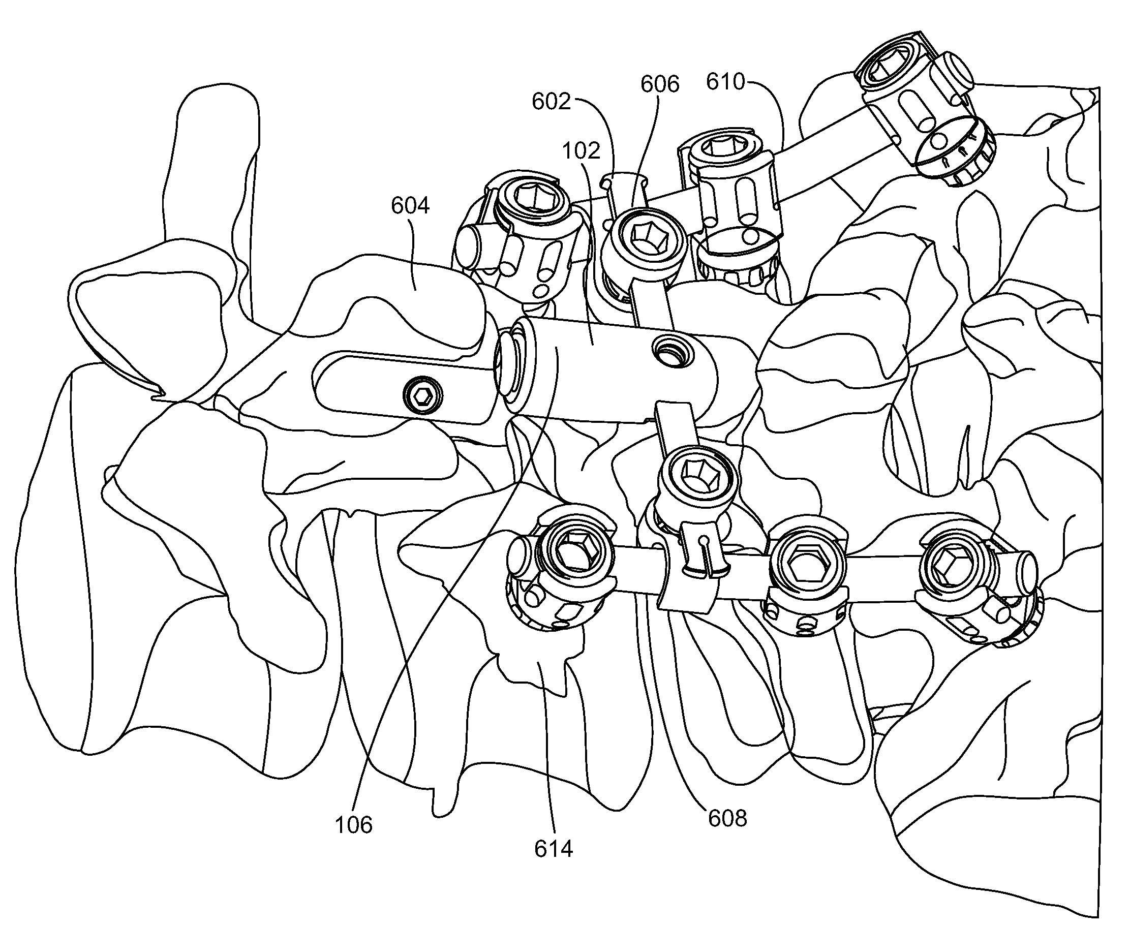
[0033]FIGS. 6A and 6B, with respect to FIGS. 1 through 5B, illustrate a front view and a side view, respectively, of the damper system 100 of FIG. 4 assembled into a vertebra according to an embodiment her...


PUM


Abstract

An orthopedic damper system and method to control the degree of flexion and/or extension motion of the mobile vertebral segment while providing additional stability to the spine. The damper system includes an anchor having a spring hitch, a spring coupled to the spring hitch, and a cap coupled to the spring. The anchor is adapted to connect to a spinous process. The spring includes an inner hollow area adapted to accommodate the spring hitch. The cap includes an opening connected to an inner cavity that is adapted to accommodate the spring and the spring hitch.

Description

BACKGROUND[0001]1. Technical Field[0002]The embodiments herein generally relate to medical devices, and, more particularly, to a spinal flexion and extension motion damper used during orthopedic surgeries.[0003]2. Description of the Related Art[0004]Patients who have a lumbar spinal fusion have an increased risk of having adjacent segment disease. Adjacent segment disease occurs after the spinal fusion in which the segment or the intervertebral disc and the facet joints are degenerated at the adjacent level above (and sometimes below) the lumbar fusion. This disease can produce severe pain that can affect the spinal cord's ability to properly function. Often, a disorder in one spinal component can lead to ultimate disorder, and finally pain in another component. These can also lead to spinal stenosis in which the spinal canal narrows and compresses the spinal cord and nerves. Laminectomy is a surgical procedure which is used for treating spinal stenosis by relieving pressure on the ...

Claims


Application Information

Patent Timeline
Patent Type & Authority Applications(United States)
IPC IPC(8): A61B17/70A61B17/58A61B17/56A61B17/08A61B17/04
CPCA61B17/7032A61B17/7049A61B17/7067A61B17/7062A61B17/7055
Inventor DURWARD, QUENTIN JOHNABDELGANY, MAHMOUD F.
Owner CUSTOM SPINE INC
Why Eureka
Try Eureka