Fixed bearing joint endoprosthesis with combined congruent - incongruent prosthetic articulations

a fixed bearing joint and prosthesis technology, applied in the field of prosthetic joints, can solve the problems of uneconomical justified added cost of multi-part tibial or patellar replacement, unfavorable patient rehabilitation, and quite elderly implants, and achieve the effects of reducing time and frequency of use, reducing contact stresses, and reducing the loading level

Inactive Publication Date: 2010-09-23
BUECHEL PAPPAS TRUST
View PDF11 Cites 27 Cited by
  • Summary
  • Abstract
  • Description
  • Claims
  • Application Information

AI Technical Summary

Benefits of technology

[0009]Improved fixed bearing articulating surfaces are possible by limiting the degree of incongruity in such devices. This may be accomplished by using a congruent, spherical surface on the medial condyle of the knee or ankle and mildly incongruent line contact on the more lightly loaded lateral condyle rather than the typical point contact on both sides used for fixed bearing designs. This design recognizes the fact that the medial condyles of both the femur and the patella of the knee joint and the medial condyle of the ankle joint are subject to greater loads than the lateral condyles thereof. The congruent contact at the more highly loaded medial condyle results in lower stress (i.e. force per unit area) due to the higher surface contact area achieved with congruency. On the other hand, the line contact at the less highly loaded lateral condyle results in acceptably low stress despite the smaller surface area due to the lower load on the lateral condyle. However, the line contact at the lateral condyles can achieve greater joint mobility without using a mobile bearing joint design.
[0011]Many patients who receive knee and ankle implants are quite elderly and inactive and thus produce loads that are substantially less than normal. This lower loading level (producing lower contact stresses for a given articulation geometry), coupled with the reduced time and frequency of use (which reduce the accumulated damage for given contact stresses) can allow articulating surfaces with a greater degree of incongruity and thus allow the use of fixed bearing components. Since fixed bearings do not require a supporting prosthetic platform, they can be fixtured directly to bone, saving the cost of the platform. The US medical care system is under considerable pressure to lower costs, and hence many hospitals would prefer to use a low cost device. A low cost, fixed bearing, device can be used as tibial or patellar components of a total knee in an elderly, inactive, patient. Therefore, the added cost of multi-part tibial or patellar replacements are not justified economically if a lower cost set of components are adequate.
[0012]An articulation surface with partially incongruent contact surfaces can produce substantially lower contact stresses than existing incongruent, fixed bearing devices. Lowering contact stresses in incongruent fixed bearing devices reduces wear and fatigue damage of the prosthetic articulating surfaces, thereby increasing their service life and increasing the population group to which such components can safely be used. The articulating surfaces of the subject invention can have similarities to the articulating surfaces shown in U.S. Pat. No. 5,871,539 and U.S. Pat. No. 6,074,425, the disclosures of which are incorporated herein by reference. However, the articulating surfaces of the subject invention are formed by means that are different from the means used to generate the articulating surfaces in these earlier patents. Additionally, the articulating surfaces of the subject invention are configured to achieve line contact in only one of the condyles of the subject invention as compared to both condyles of the earlier patents. Thus, this invention improves the fixed bearing articulating surfaces.

Problems solved by technology

Many patients who receive knee and ankle implants are quite elderly and inactive and thus produce loads that are substantially less than normal.
Therefore, the added cost of multi-part tibial or patellar replacements are not justified economically if a lower cost set of components are adequate.

Method used


Image

  • Fixed bearing joint endoprosthesis with combined congruent - incongruent prosthetic articulations
  • Fixed bearing joint endoprosthesis with combined congruent - incongruent prosthetic articulations
  • Fixed bearing joint endoprosthesis with combined congruent - incongruent prosthetic articulations

Examples


Embodiment Construction

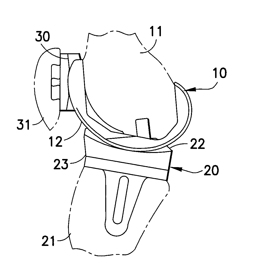
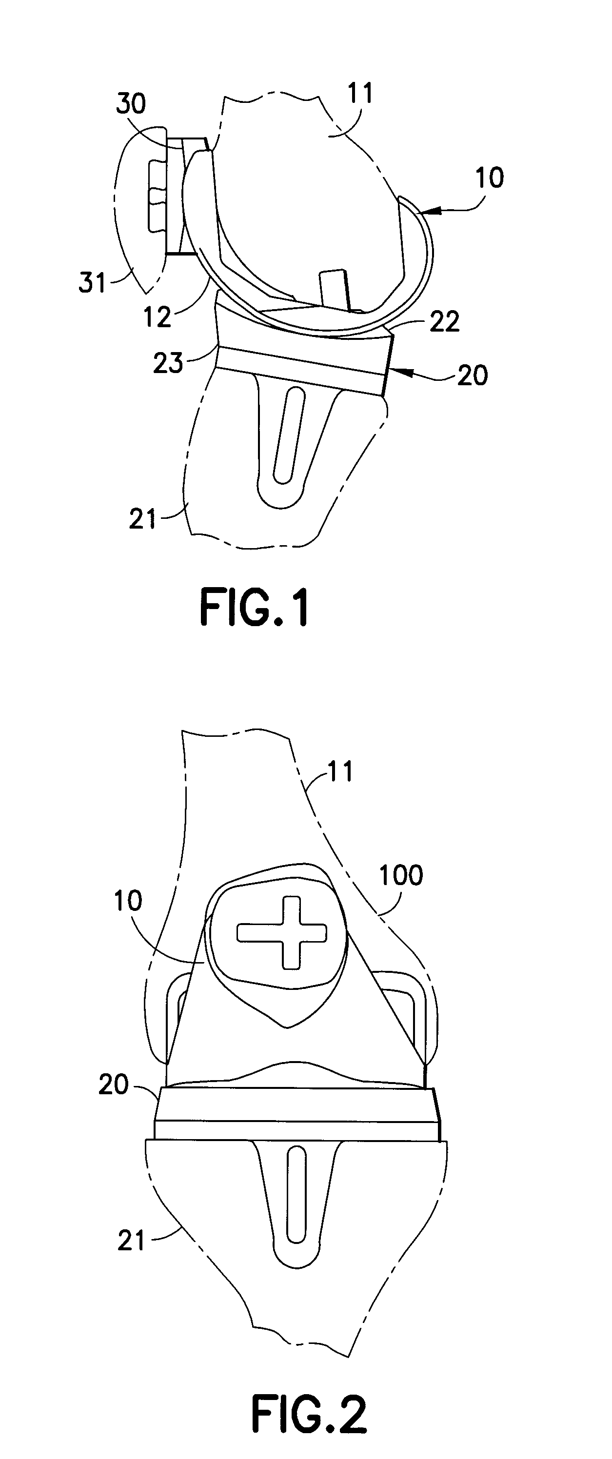
[0044]FIGS. 1 and 2 show a cruciate sacrificing total knee replacement prosthesis 100. The knee prosthesis has a metallic (Co—Cr or Titanium alloy) femoral component 10 which is fixtured to the distal femur 11, a plastic (UHMWPe) tibial component 20 fixtured to the proximal tibia 21, and a plastic patellar component 30 fixtured to the posterior patella 31. Alternately, both components may be metallic, ceramic coated metal or ceramic.

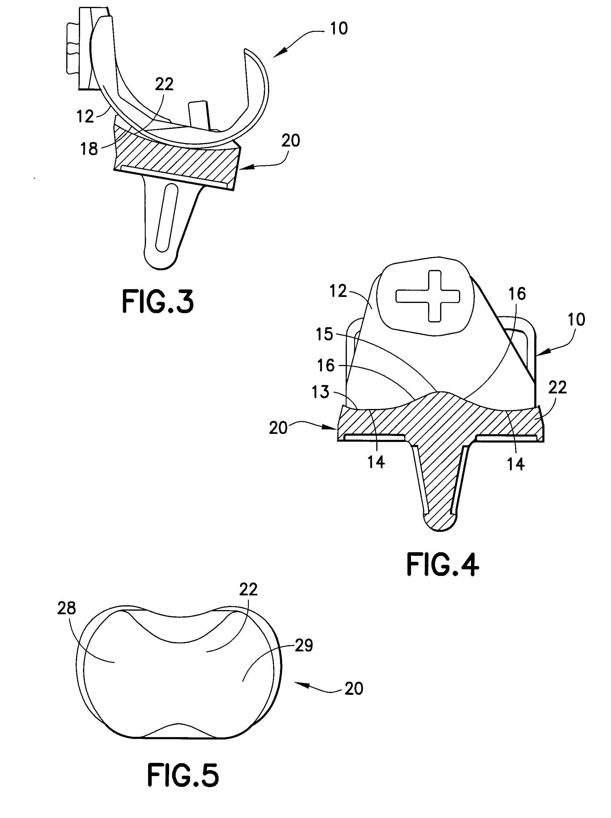
[0045]The geometry of the femoral articulating surface 12 of the femoral component 10, as shown in FIGS. 3 and 4, is a compound surface of revolution generated by revolving a generating curve 13 consisting of radii 14, radius 15, and connecting tangents 16. This geometry is described in additional detail in the above-referenced patents, including U.S. Pat. No. 4,309,778 and U.S. Pat. No. 5,507,820.

[0046]The tibial component 20 has a tibial articulating surface 22 that is generated using the same generating curve 13, except for different connecting tangen...


PUM

PropertyMeasurementUnit
radiiaaaaaaaaaa
radiusaaaaaaaaaa
metallicaaaaaaaaaa

Abstract

An orthopedic joint replacement has first and second joint components that can be placed in load-bearing articulation with one another. The first joint component has first and second convex spherical condylar segments defining first and second radii. The second joint component has a spherical first concave condylar segment with a radius equal to the radius of the first convex spherical condylar segment. The second joint component also has a non-spherical second concave condylar segment. The first convex spherical condylar segment of the first joint component is in congruent contact with the first spherical concave condylar segment of the second joint component. The second spherical convex condylar segment of the first joint component is in line contact with the non-spherical concave condylar segment of the second joint component.

Description

[0001]This application claims priority on U.S. Provisional Patent Appl. No. 61 / 098,824 filed on Sep. 22, 2008, the entire contents of which are incorporated herein by reference.BACKGROUND OF THE INVENTION[0002]1. Field of the Invention[0003]The invention relates to prosthetic joints, such as prosthetic knee joints.[0004]2. Description of the Related Art[0005]A typical prosthetic knee includes a tibial component for mounting to the resected proximal end of the tibia, a femoral component for mounting to the resected distal end of the femur, a bearing between the tibial and femoral components and a patellar component mounted to the posterior face of the patella. The tibial and femoral components typically are made of metal and the bearing typically is made of plastic, such as UHMWPe. The proximal or superior surface of the bearing is formed to define medial and lateral concave regions. The distal or inferior surface of the femoral component is formed to define medial and lateral convex...

Claims


Application Information

Patent Timeline
Patent Type & Authority Applications(United States)
IPC IPC(8): A61F2/38
CPCA61F2/3094A61F2310/00592A61F2/3804A61F2/3877A61F2/4202A61F2/4241A61F2002/30116A61F2002/30245A61F2002/30329A61F2002/30604A61F2220/0025A61F2230/0006A61F2230/0071A61F2310/00023A61F2310/00029A61F2310/00179A61F2/38
Inventor PAPPAS, MICHAEL J.
Owner BUECHEL PAPPAS TRUST
Why Eureka
Try Eureka