Method and apparatus for lumbar support with integrated actuator housing

a technology of actuator housing and lumbar support, which is applied in the direction of chairs, rocking chairs, transportation and packaging, etc., can solve the problems of increasing the cost of materials, increasing the likelihood of component failure, and shortening the life of the device, so as to reduce the need for additional components, increase the degree of convexity of the pressure surface, and save space

Inactive Publication Date: 2005-05-17
L & P PROPERTY MANAGEMENT CO
View PDF3 Cites 31 Cited by
  • Summary
  • Abstract
  • Description
  • Claims
  • Application Information

AI Technical Summary

Benefits of technology

[0012]Prior configurations of lumbar supports generally located the actuator motor outside the profile of the pressure surface. The present invention locates the actuator motor within the profile of the pressure surface, saving space. Moreover, the present invention actually incorporates the housing for the electric motor on the back of the pressure surface itself, reducing the need for additional components and assembly time to attach the motor to a seat-frame.
[0013]The pressure surface / motor housing is a single molded plastic unit. The actuator motor is anchored in its housing on the back of the pressure surface. Upon engagement of the motor it draws a traction cable that is directed to engage both ends of the pressure surface in order to draw them together. The longer the motor is engaged, the closer together the cable draws the ends of the pressure surface, and thereby the greater the degree of convexity of the pressure surface. Releasing the tension lengthens the traction cable and flattens the pressure surface. In this manner a seat occupant can control the degree of lumbar support.
[0014]The present invention reduces the number of components necessary to assemble a lumbar support unit. It is compact in size for ease of packaging, and ease of incorporation into a variety of different seats. The present invention reduces costs required to manufacture, sell, assemble, maintain and operate the lumbar support. The present invention eases and streamlines the manufacture of the lumbar supports and of seats incorporating it, to lower production cost and increase durability and useful life.
[0015]The present invention may be incorporated easily with existing components, for example, seat frames, and with future seats that may have less space available within them. It does not require guide wires, outside actuators, attachment brackets or long cables.

Problems solved by technology

The multiplicity of moving parts in prior art lumbar supports complicates manufacture, increases expense of materials necessary, increases the likelihood of component failure and shortens the life span of the devices.
Moreover, prior art lumbar supports require a relatively large amount of space to 15 accommodate the relatively cumbersome tensioning or compression apparatuses, together with the frameworks necessary for their support.
As seat designs are modified to incorporate more comfort devices, such as duct work for heating and cooling, the amount of space available inside seats for lumbar support devices shrinks.

Method used


Image

  • Method and apparatus for lumbar support with integrated actuator housing
  • Method and apparatus for lumbar support with integrated actuator housing
  • Method and apparatus for lumbar support with integrated actuator housing

Examples


Embodiment Construction

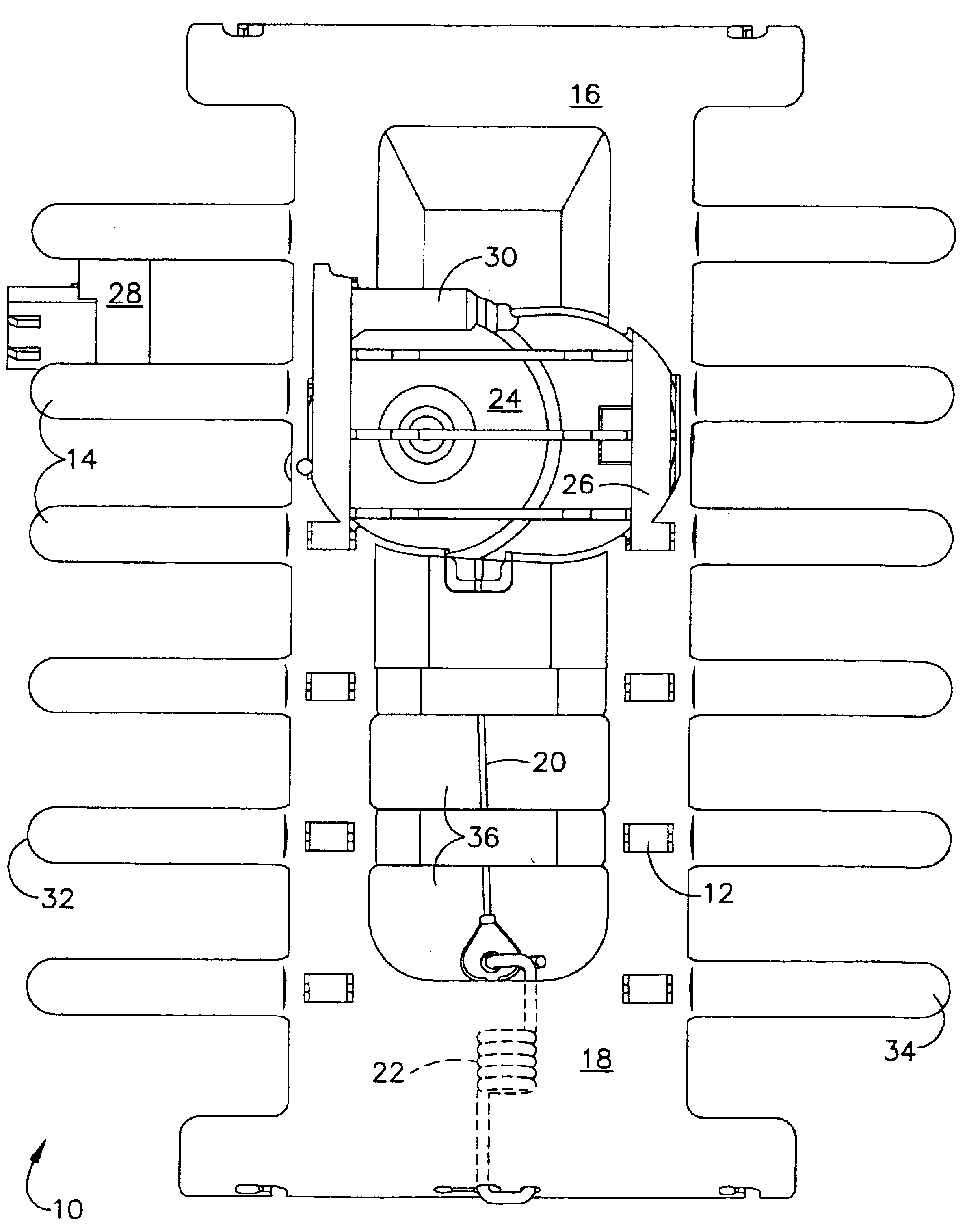
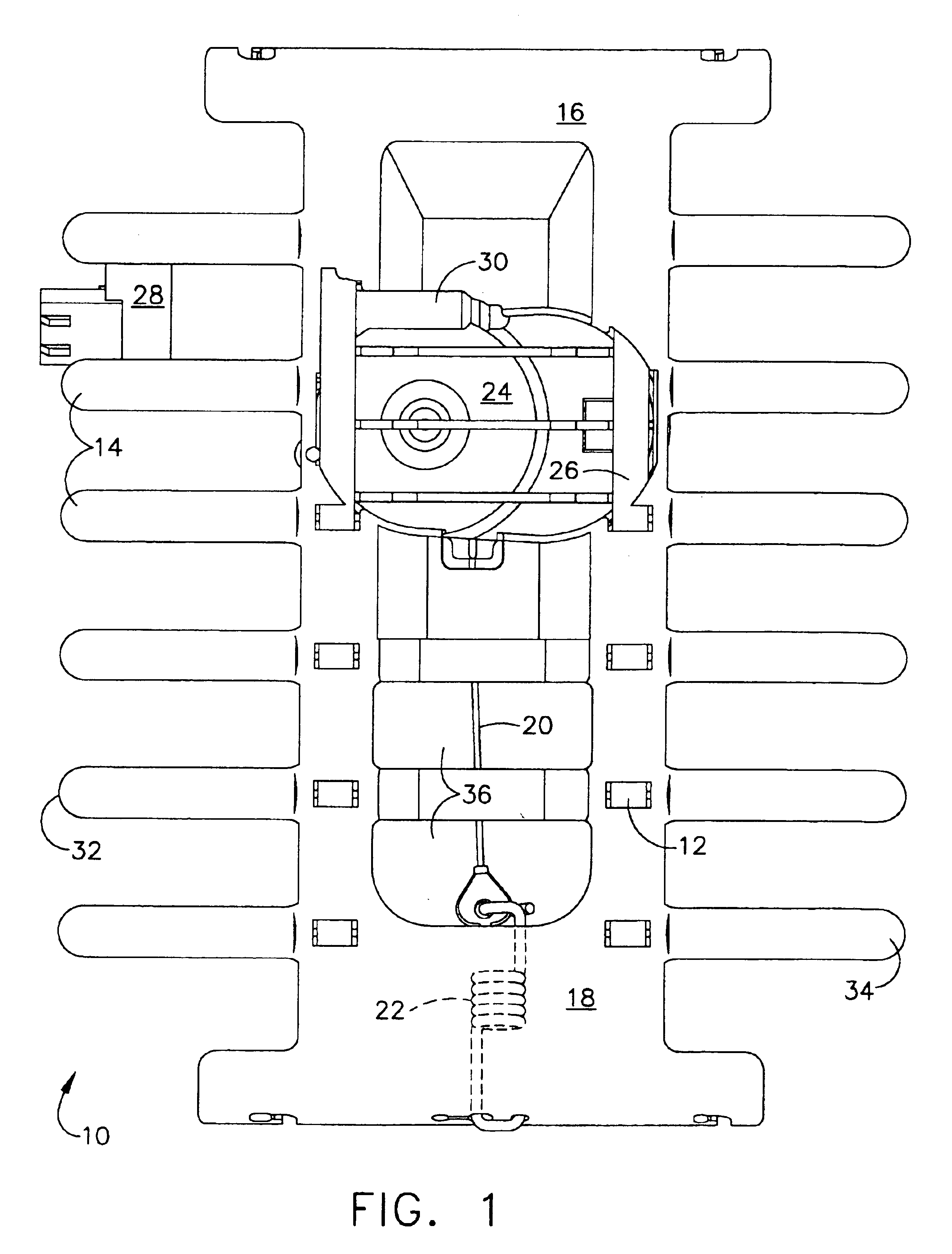
[0034]Referring to the accompanying drawings in which like reference numbers indicate like elements, FIG. 1 is a front view of the lumbar support with integrated actuator housing of the present invention.

[0035]Lumbar support devices are manufactured in a variety of configurations. One type of lumbar support mechanism is characterized by an arching pressure surface which is with an upper region and a lower region. The upper region and lower region are brought closer together by any of a variety of mechanical means, and this closing movement of the ends of the pressure surface bows the pressure surface outwards in an arch that is convex towards the seat occupant. The mechanism for arching the pressure surface can compress the encapsulated ends, or draw them together by traction. The depicted embodiment is a development of the traction family of arching lumbar supports, although a compression embodiment is also considered to be within the scope of the present invention.

[0036]Traction i...


PUM


Abstract

A lumbar support for a seat includes an archable pressure surface having an upper region and a lower region and a force actuator such as an electric motor. The force actuator is held in a housing. The actuator housing is fixedly attached to said archable pressure surface in a compact design. A force transmission element such as a cable is connected to at least one of the upper and lower regions of the pressure surface and the force transmission element is also connected to the actuator. When force is applied by the force actuator to the cable, the pressure surface arches from a substantially flat position to an arched position.

Description

CROSS-REFERENCE TO RELATED APPLICATIONS[0001]This application is a Continuation of application Ser. No. 09 / 993,579, filed Nov. 16, 2001, now U.S. Pat. No. 6,676,214 and claims priority thereto.STATEMENT REGARDING FEDERALLY SPONSORED RESEARCH OR DEVELOPMENT[0002]Not ApplicableBACKGROUND OF THE INVENTION[0003]1. Field of the Invention[0004]This invention relates generally to ergonomic weight support devices, especially arching lumbar supports for seats.[0005]2. Related Art[0006]Lumbar supports for seats, particularly automobile seats, are known. See U.S. Pat. Nos. 5,050,930; 5,397,164; 5,498,063; 5,626,390; 5,775,773; 6,003,941; 4,354,709; 4,452,485; 4,632,454; 4,880,271; GB 2 013 487A and D 169 293 Bi. These devises all have in common one or more flexible members that may be flexed in order to create a convex surface with its apex towards the lumbar spine of a human being sitting in the seat into which the device is incorporated. This convex flexion is induced by any of a great varie...

Claims


Application Information

Patent Timeline
Patent Type & Authority Patents(United States)
IPC IPC(8): A47C7/46B60N2/62B60N2/48B60N2/66B60N2/64
CPCB60N2/48B60N2/66B60N2/62B60N2/666B60N2/6671B60N2/6673B60N2/80
Inventor MCMILLEN, ROBERTMESZAROS, EDWARD J. L.
Owner L & P PROPERTY MANAGEMENT CO
Why Eureka
Try Eureka