Outlet silencer and heat recovery structures for gas turbine

a technology of exhaust silencer and heat recovery structure, which is applied in the direction of machines/engines, steam generation using hot heat carriers, lighting and heating apparatus, etc., can solve the problems of not being efficient in reducing the level of sound exiting from the gas turbine, the silencer duct located along the path of the by-pass stack is useless in reducing the amount of noise generated by the turbine and exiting from the hot air outlet, etc. to achieve the effect of reducing the sound level

Inactive Publication Date: 2005-02-08
M & I POWER TECH
View PDF26 Cites 133 Cited by
  • Summary
  • Abstract
  • Description
  • Claims
  • Application Information

AI Technical Summary

Benefits of technology

According to one aspect of the invention, a sound attenuating duct unit suitable for connection to an airflow outlet of a machine having a rotating axial flow member includes a duct housing having exterior sides and two opposite ends. An air inlet is located in one of these ends and the housing further includes first and second air outlets with the first air outlet located at the other end of the housing. The air inlet is adapted for connection to the airflow outlet of the machine. Interior walls are arranged in the housing and define a main airflow passageway system which extends from the air inlet to both of the first and second outlets. Sound absorbing material is arranged between the interior wails and the exterior sides of the duct housing and sound attenuating members are mounted in the airflow passageway system. The sound attenuating

Problems solved by technology

For example, the known outlet stack arrangements, even if they are provided with some form of duct silencer, are not very efficient at reducing the level of sound exiting from the gas turbine.
One reason for this is that the silencer module, if it is provided at all, may be spaced a substantial distance from the outlet of the gas turbine and, due to its location, the silencer duct is not particularly efficient in terms of sound reduction due to the transmission of sound through the walls of the ducts located upstream of the silencer.
Also, if the diverter damper is directing the hot air flow into a heat recovery apparatus rather than straight through the by-pass stack, a silencer duct located along the path for the by-pass stack will

Method used


Image

  • Outlet silencer and heat recovery structures for gas turbine
  • Outlet silencer and heat recovery structures for gas turbine
  • Outlet silencer and heat recovery structures for gas turbine

Examples


Embodiment Construction

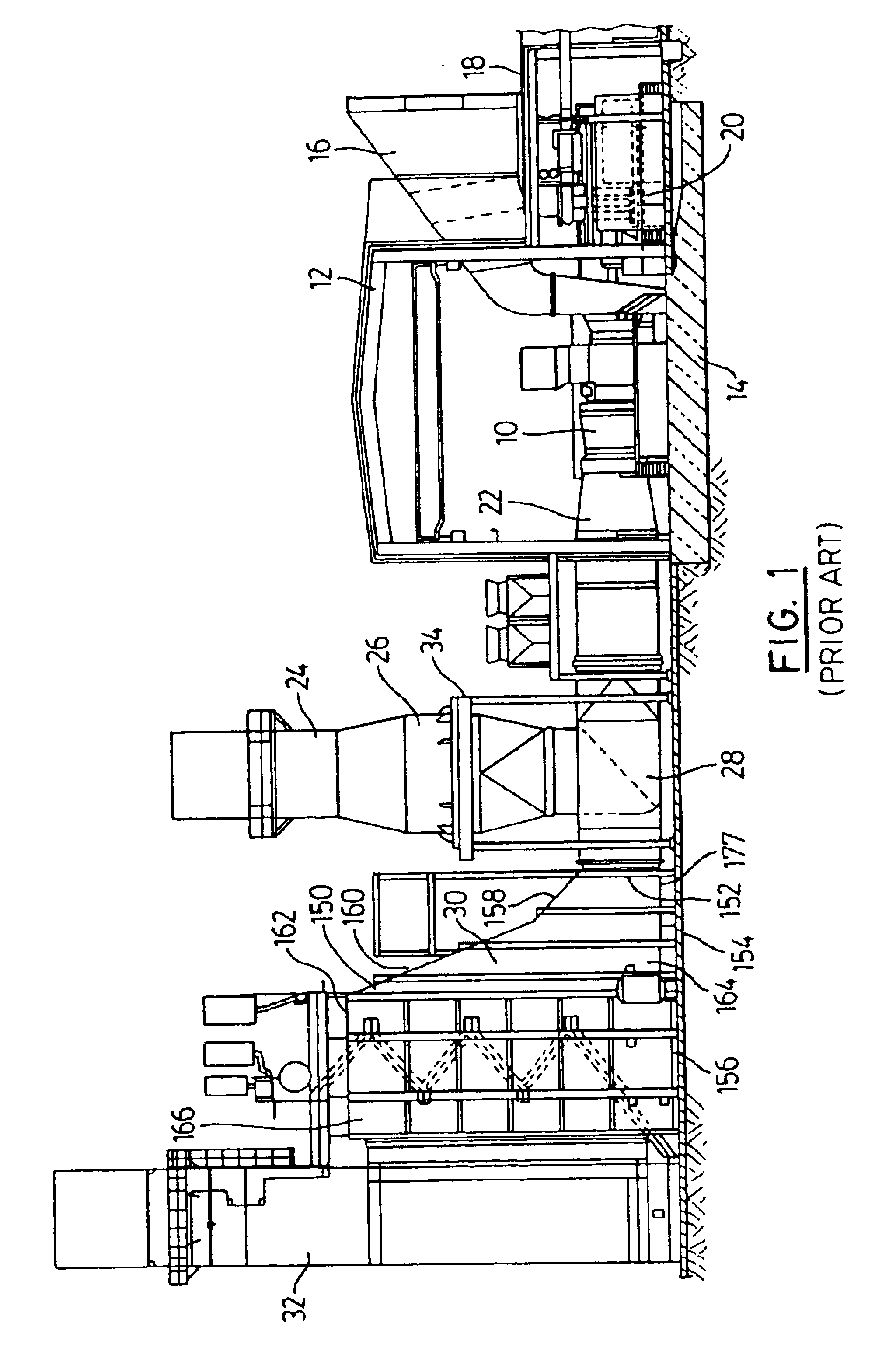
Illustrated in FIG. 1 is a schematic view of an electrical power generating system employing a large, stationary gas turbine 10. The gas turbine can be of standard construction and it can be protected by means of a building or structure 12. The turbine can be rigidly mounted on a thick concrete pad 14. Intake air for the turbine is drawn in through an air intake filter arrangement 16 which can be mounted on a suitable support frame 18. Arranged below the filter arrangement 16 is a gas turbine generator 20 which can be fitted with a suitable generator circuit breaker. A circular hot air outlet for the turbine is located at 22. Connected downstream of the turbine outlet is a bypass stack 24 through which the hot exhaust gases from the turbine can be passed, if required or appropriate. As explained further below, this stack can contain a duct silencer located in duct section 26 which has an enlarged horizontal cross-section. Located below the section 26 is a by-pass stack module 28 whi...


PUM


Abstract

A sound attenuating duct unit suitable for connection to an outlet of a gas turbine and an improved heat recovery apparatus for use with such a turbine are disclosed. The former unit includes a duct housing having exterior sides, an air inlet at one end and first and second air outlets. Interior walls define a main airflow passageway extending from the air inlet to both of the outlets. Sound absorbing and heat insulation material is arranged between these walls and the exterior sides. Sound attenuating members are mounted in the passageway and a diverter damper is mounted in the housing and is able to direct air flow to either one of the air outlets. The sound attenuating members are mounted between the diverter damper and the air inlet. The heat recovery apparatus includes a series of aerodynamic diffusers mounted in a housing adjacent an air flow inlet connectable to the gas turbine.

Description

BACKGROUND OF THE INVENTIONThis invention relates to duct units and other devices that can be connected to an air flow outlet of a machine having a rotating axial flow member, for example, a gas turbine and the invention further includes heat recovery apparatus.The use of large gas turbines for generating electrical power is well known in the power generation art. These large gas turbines can be mounted horizontally in a building or other shelter that provides protection to the turbine against the elements. The outlet for the turbine, through which passes a hot air flow at substantial speed, can be connected to a diffuser duct of cylindrical configuration and then to a transition duct which transforms the hot air outlet passageway from a circular cross-section to a rectangular cross-section. A damper can then be provided, which damper in a first position can direct the hot air flow upwardly through a suitable outlet stack (also referred to as a by-pass stack) which can, in some case...

Claims


Application Information

Patent Timeline
IPC IPC(8): F01D25/30F01D25/00F02C7/08F22B1/18F22B1/00F28F27/00F28F27/02F01N1/24F01N5/00F01N5/02
CPCF01D25/30F28F9/0263F02C7/08F22B1/1815F01N1/24F01N5/02F01N2310/02
Inventor HAN, MING HUIYAZICI, MUAMMER
Owner M & I POWER TECH
Why Eureka
Try Eureka