Circuit board, camera module and method for marking circuit board

A technology of camera modules and circuit boards, which is applied in the fields of printed circuit, printed circuit, printed circuit manufacturing, etc. It can solve the problems of easy damage and falling off of barcode or number label, inconvenient long-term storage, high price of steel sheet, etc., to achieve enhanced bonding Fixing ability, effect of increasing coating area

Inactive Publication Date: 2019-12-17
TRIPLE WIN TECHSHENZHEN CO LTD +1
View PDF5 Cites 0 Cited by
  • Summary
  • Abstract
  • Description
  • Claims
  • Application Information

AI Technical Summary

Problems solved by technology

However, the barcode or number label is easy to damage and fall off, which is not convenient for long-term storage; while laser printing the QR code on the PCB steel sheet, the price of the steel sheet is relatively high, which increases the overall cost of the camera module

Method used


Image

  • Circuit board, camera module and method for marking circuit board
  • Circuit board, camera module and method for marking circuit board
  • Circuit board, camera module and method for marking circuit board

Examples


Embodiment Construction

[0017] The first embodiment of the present invention will be further described in detail below in conjunction with the accompanying drawings.

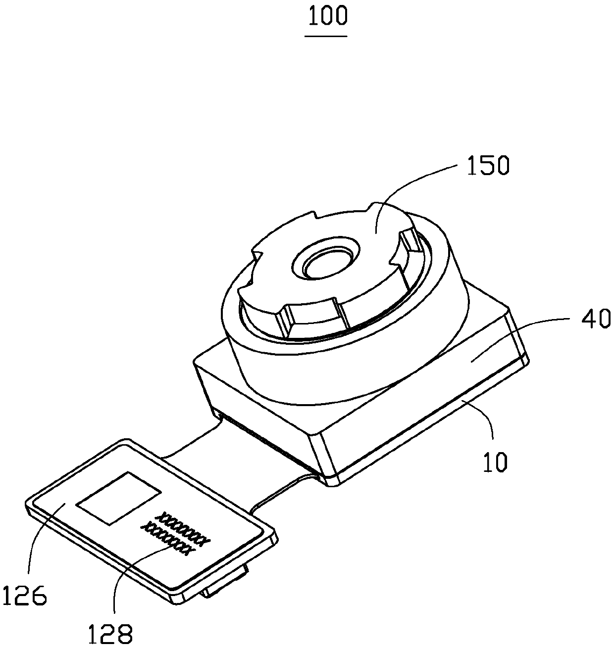
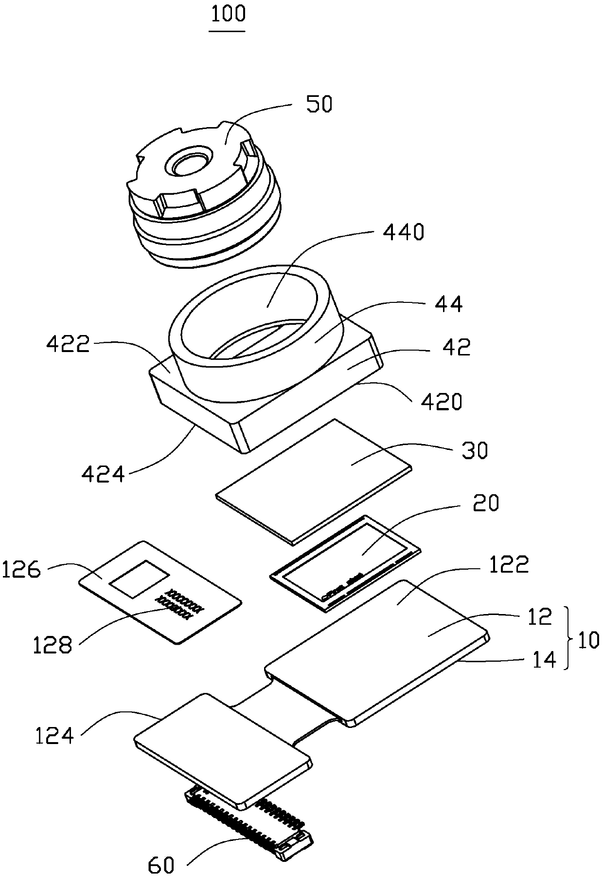
[0018] see figure 1 and figure 2 , is the camera module 100 provided by the embodiment of the present invention. The camera module 100 includes a circuit board 10 , an image sensor 20 , a protection plate 30 , a lens base 40 and a lens barrel 50 .

[0019] The circuit board 10 includes an upper surface 12 and a lower surface 14 . The upper surface 12 and the lower surface 14 are located on opposite sides of the circuit board 10 . In this embodiment, the upper surface 12 is parallel to the lower surface 14 . The upper surface 12 includes an assembly area 122 and a label area 124 . The assembly area 122 and the labeling area 124 are connected to each other. The assembly area 122 is used for installing components of the camera module 100 . The marking area 124 is used for marking the circuit board 10 . A paint layer 126 is coated...


PUM


Abstract

The invention relates to a circuit board, which comprises an assembly area and a marking area. The assembly area is used for mounting elements; and the marking area is used for marking the circuit board. The circuit board is characterized in that one surface of the marking area is coated with a paint layer, and a two-dimensional code is printed on the paint layer. The invention also relates to a camera module using the circuit board and a method for marking the circuit board.

Description

technical field [0001] The invention relates to a circuit board and a camera module, in particular to a circuit board for marking, a method for marking the circuit board and a camera module using the circuit board. Background technique [0002] A camera module generally includes a carrier substrate, an image sensor, a lens mount and a lens barrel. The image sensor and the mirror base are fixed on the substrate. The lens barrel is accommodated in the lens holder. In the production process, in order to facilitate the tracking of the camera module, the label with a barcode or number is pasted on the camera module in the production line or the two-dimensional code is laser printed on the steel sheet of the circuit board PCB. Numbering and tracking of camera modules. However, the barcode or serial number label is easy to damage and fall off, and it is not convenient for long-term storage; while laser printing the QR code on the PCB steel sheet, the price of the steel sheet is ...

Claims


Application Information

Patent Timeline
Patent Type & Authority Applications(China)
IPC IPC(8): H05K1/02H05K3/30H04N5/225
CPCH05K1/0269H05K3/30H04N23/54H04N23/57H04N23/55H05K2201/10151H05K2201/10121H05K1/148H05K2201/10189H05K2203/107H04N23/52H05K1/0266H05K2201/09918H05K1/189
Inventor 陈信文丁盛杰李静伟宋建超
Owner TRIPLE WIN TECHSHENZHEN CO LTD
Why Eureka
Try Eureka