Portable design drawing showing stand for industrial design and application method thereof
A design drawing and industrial design technology, applied in application, display hangers, display shelves, etc., can solve problems such as inapplicability of tiled display methods and large space occupation, so as to avoid small number of displays, large occupied area, and The effect of increasing the number of impressions
- Summary
- Abstract
- Description
- Claims
- Application Information
AI Technical Summary
Problems solved by technology
Method used
Image
Examples
Embodiment 1
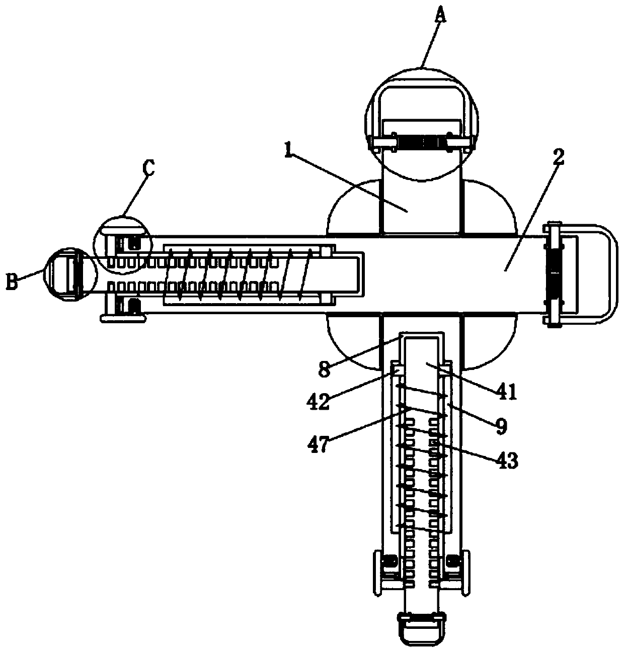
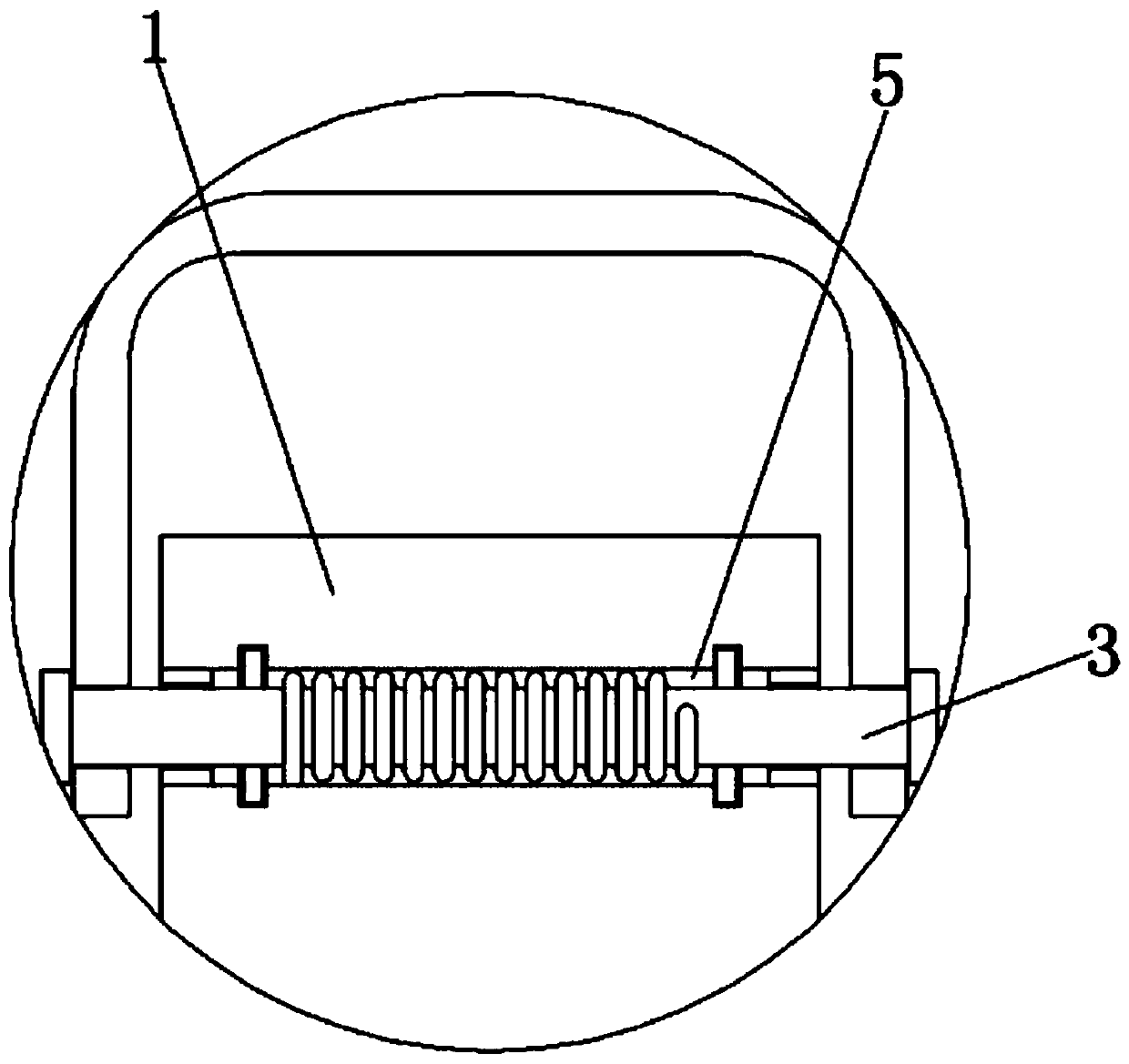
[0034] Such as Figure 1-5 As shown, a portable design drawing display stand for industrial design includes a first fixed column 1 and a second fixed column 2, a first clamping mechanism 3 is arranged at one end of the top of the first fixed column 1, and a first clamping mechanism 3 is arranged at the bottom of the first fixed column 1. One end of the first fixed column 1 is provided with an extension mechanism 4, and one end of the top of the first fixed column 1 is provided with a first rotation hole 5 communicating with the left and right sides thereof, and the two sides of the inner cavity of the first rotation hole 5 are symmetrically provided with a first stop ring 6, The two ends of the four sides of the inner wall of the first rotating hole 5 are symmetrically provided with an annular limiting groove 7, the middle of the bottom of the first fixed column 1 is provided with a first moving groove 8, and the middle of the first moving groove 8 inner wall is symmetrically pro...
Embodiment 2
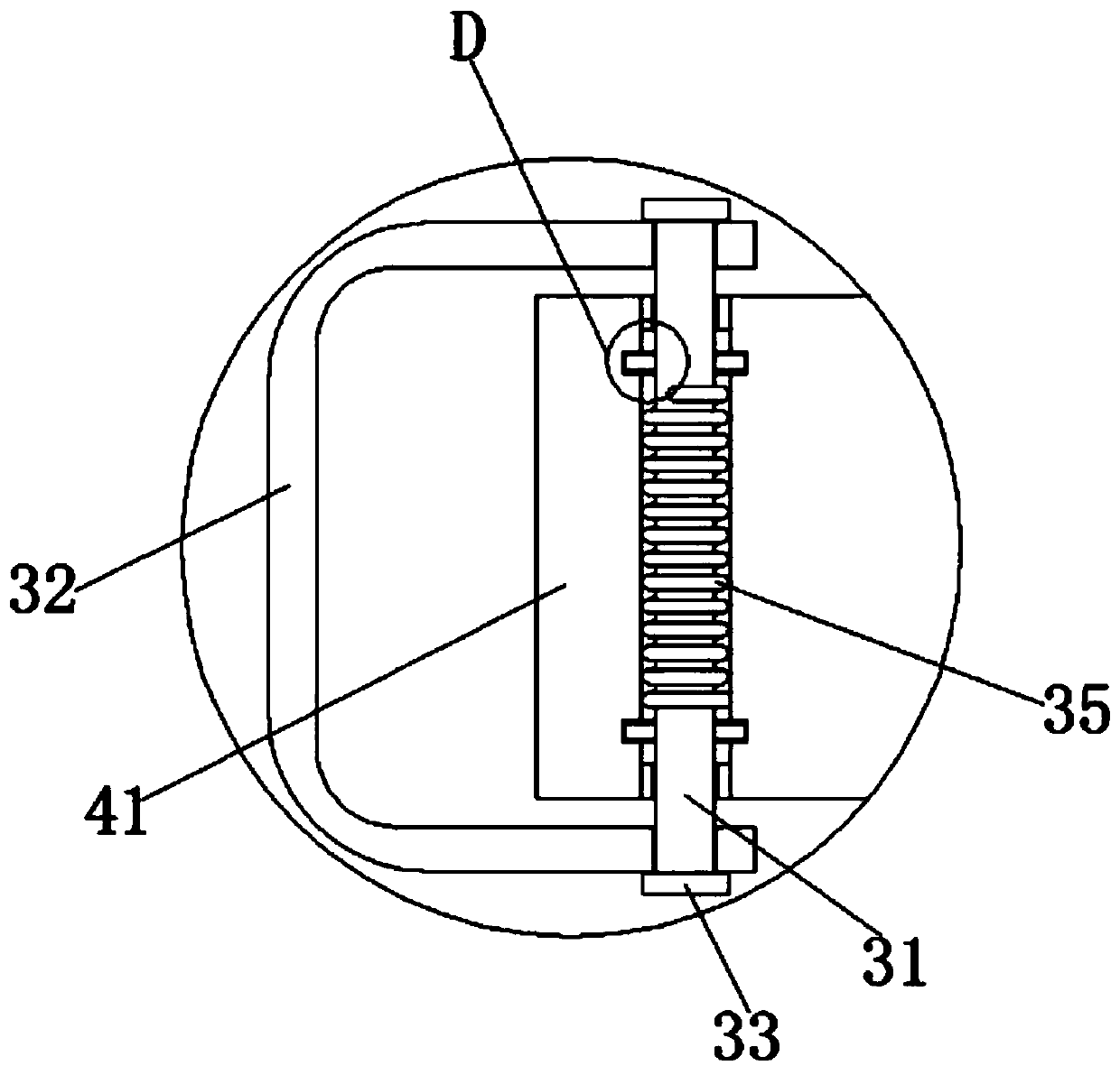
[0036] On the basis of Embodiment 1, the first clamping mechanism 3 includes a support rod 31, the top of the support rod 31 is provided with a clamping rod 32, and the two ends of the support rod 31 are symmetrically fixedly connected with a clamping cap 33, and the top of the support rod 31 is connected to the top of the support rod 31. Both sides of the bottom are fixedly connected with limiting blocks 34 symmetrically, and a torsion spring 35 is sleeved in the middle of the support rod 31 .
Embodiment 3
[0038] On the basis of Embodiment 1-2, the support rod 31 is arranged inside the first rotation hole 5, and the two ends of the support rod 31 respectively pass through the first limit rings 6 on both sides and extend to the outside of the first fixed column 1 , the support rod 31 fits with the first limit ring 6 .
PUM
 Abstract
Description
Claims
Application Information
 - R&D
- Intellectual Property
- Life Sciences
- Materials
- Tech Scout
- Unparalleled Data Quality
- Higher Quality Content
- 60% Fewer Hallucinations
Browse by: Latest US Patents, China's latest patents, Technical Efficacy Thesaurus, Application Domain, Technology Topic, Popular Technical Reports.
© 2025 PatSnap. All rights reserved.Legal|Privacy policy|Modern Slavery Act Transparency Statement|Sitemap|About US| Contact US: help@patsnap.com


