Stamping equipment with waste collection function

A technology for stamping equipment and waste collection, applied in the field of stamping equipment, can solve the problems of time-consuming and laborious, no clamping device, increased labor force, etc., and achieve the effect of convenient use, reasonable structure and labor saving.

Active Publication Date: 2019-12-20
江西晖旭实业有限公司
View PDF13 Cites 3 Cited by
  • Summary
  • Abstract
  • Description
  • Claims
  • Application Information

AI Technical Summary

Problems solved by technology

[0004] The purpose of the present invention is to solve the problems in the prior art that the traditional stamping equipment does not have a good clamping device when punching materials, so that deviation occurs during the punching pro

Method used


Image

  • Stamping equipment with waste collection function
  • Stamping equipment with waste collection function
  • Stamping equipment with waste collection function

Examples


Embodiment 1

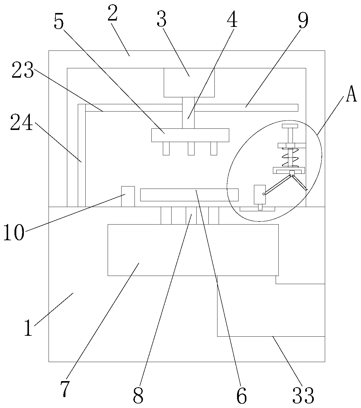
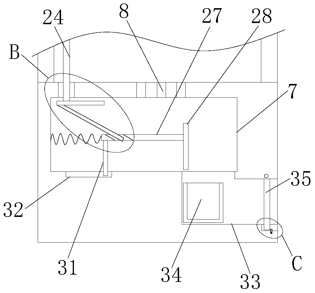
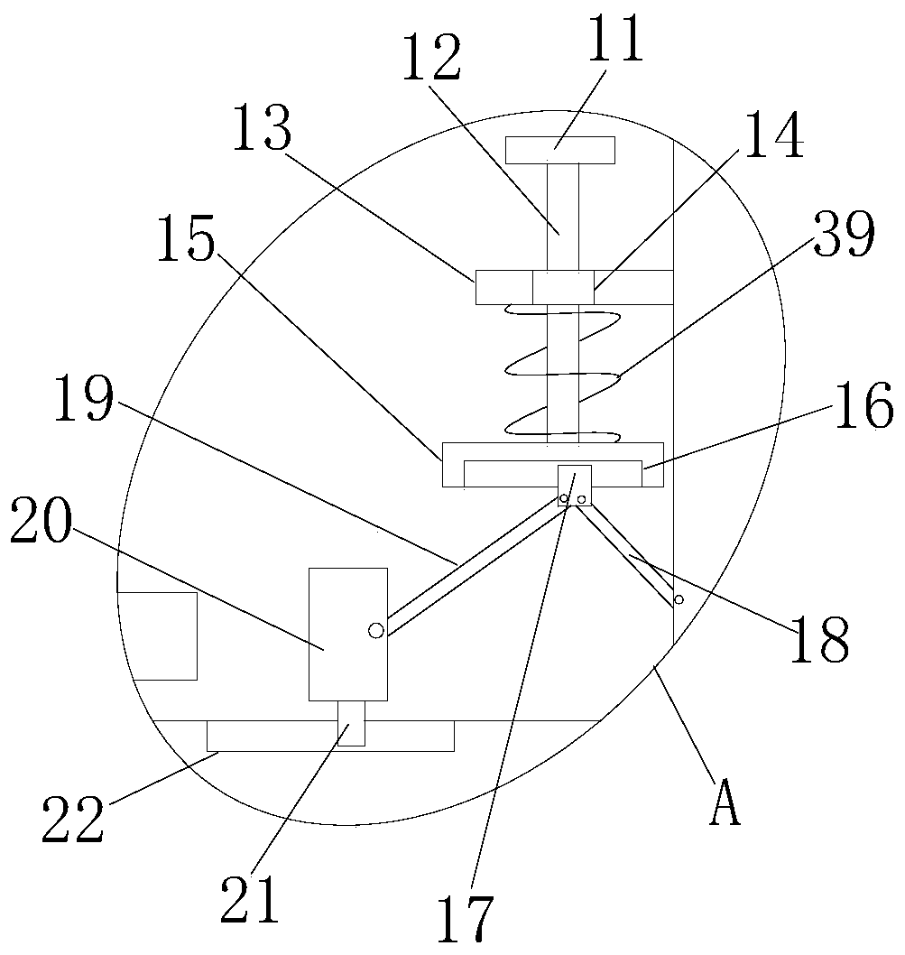
[0027] refer to Figure 1-5 , a kind of stamping equipment with the function of collecting waste materials, comprising a device body 1, an equipment frame 2 is arranged on the device body 1, a motor 3 is arranged on the device frame 2, a telescopic rod 4 is arranged on the motor 3, and the bottom end of the telescopic rod 4 A stamping head 5 is provided, a plate 6 is provided on the equipment body 1, a punching hole 8 is opened on the top side of the equipment body 1, a first installation rod 9 is fixedly installed on one side of the telescopic rod 4, and a movable installation is installed on one side of the equipment rack 2. There is a pressing plate 11, the top side of the pressing plate 11 is adapted to the first installation rod 9, the bottom side of the pressing plate 11 is fixedly equipped with a moving bar 12, and the bottom end of the moving bar 12 is fixedly equipped with a mounting block 15, and one side of the mounting block 15 A connecting rod 19 is installed mova...

Embodiment 2

[0038] refer to Figure 1-5 , a kind of stamping equipment with the function of collecting waste materials, comprising a device body 1, an equipment frame 2 is arranged on the device body 1, a motor 3 is arranged on the device frame 2, a telescopic rod 4 is arranged on the motor 3, and the bottom end of the telescopic rod 4 A stamping head 5 is provided, a plate 6 is provided on the equipment body 1, a punching hole 8 is opened on the top side of the equipment body 1, a first installation rod 9 is fixedly installed on one side of the telescopic rod 4 by welding, and a first installation rod 9 is fixedly installed on one side of the equipment rack 2. A pressing plate 11 is movable, and the top side of the pressing plate 11 is adapted to the first installation rod 9. The bottom side of the pressing plate 11 is fixedly equipped with a moving bar 12 by welding, and the bottom end of the moving bar 12 is fixedly installed with a mounting block 15 by welding. One side of the mountin...


PUM


Abstract

The invention belongs to the field of stamping equipment, and particularly discloses stamping equipment with a waste collection function. The following scheme is disclosed with regard to the problemsthat a device is not greatly clamped when a material is punched by existing stamping equipment, and moreover, manual collection treatment needs to be carried out on waste after the punching, so that the labor is increased: the stamping equipment with the waste collection function comprises an equipment body, wherein an equipment frame is arranged on the equipment body; a motor is arranged on the equipment frame; a telescopic rod is arranged on the motor; a stamping head is arranged at the bottom end of the telescopic rod; a plate is arranged on the equipment body; a stamping hole is formed inthe top side of the equipment body; a first installation rod is fixedly installed at one side of the telescopic rod; a press plate is movably installed at one side of the equipment frame; the top sideof the press plate is adaptive to the first installation rod; a movable rod is fixedly installed at the bottom side of the press plate; and an installation block is fixedly installed at the bottom end of the movable rod. The stamping equipment with the waste collection function is reasonable in structure; working personnel can treat the waste only by opening a cover plate; and the waste can be automatically collected, so that the time and labor are saved, the labor is saved, and the stamping equipment with the waste collection function is convenient to use.

Description

technical field [0001] The invention relates to the technical field of stamping equipment, in particular to a stamping equipment with the function of collecting waste materials. Background technique [0002] Stamping is a forming processing method that applies external force to plates, strips, pipes and profiles by presses and molds to cause plastic deformation or separation to obtain workpieces (stamping parts) of required shape and size. [0003] The patent with the publication number of CN106734530B discloses an automatic punching equipment, the automatic punching equipment includes a base, a punching assembly, and a feeding assembly, a punching platform is formed on the base and a supporting part is protruded, and the punching platform has a A feeding channel is formed, and a plurality of punching holes are opened on the surface of the punching platform. The punching assembly includes a driving member and a punch, and the feeding assembly includes a pulling member and a ...

Claims


Application Information

Patent Timeline
IPC IPC(8): B21D28/34B21D28/26B21D28/04B21D43/20
CPCB21D28/04B21D28/26B21D28/34B21D43/20
Inventor 罗峰
Owner 江西晖旭实业有限公司
Why Eureka
Try Eureka